
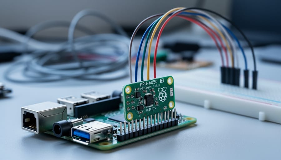
Integrating a gyroscope sensor with your Raspberry Pi takes about 30 minutes and requires only basic wiring skills. You’ll connect the sensor via I2C or SPI protocol, install a Python library, and run a short script to start capturing orientation and motion data. This combination transforms your Raspberry Pi into a motion-sensing platform capable of powering drones, self-balancing robots, gesture controllers, and navigation systems.
Gyroscope sensors measure rotational velocity across three axes, providing real-time data about how your device tilts, spins, or changes orientation. When paired with a Raspberry Pi’s GPIO pins and processing power, these sensors enable projects that respond to physical movement. The most popular choice for hobbyists is the MPU-6050, a combined gyroscope and accelerometer module that costs under ten dollars and communicates through the I2C protocol your Raspberry Pi already supports.
This guide walks you through the complete setup process. You’ll learn which sensors work best with different Raspberry Pi models, how to physically wire the connections, configure I2C communication, install the necessary Python libraries, and write code to capture and interpret sensor data. We’ve included troubleshooting tips for common issues like incorrect wiring and I2C detection failures. Whether you’re building a flight controller or experimenting with motion tracking, you’ll have a working gyroscope sensor reading data by the end of this tutorial.
What You’ll Need: Hardware and Software Requirements
You’ll need both hardware and software to connect your gyroscope sensor successfully. On the hardware side, start with any Raspberry Pi model that supports GPIO pins, the Pi 3, Pi 4, or Pi Zero W all work perfectly, though the Pi 4 offers better processing power for complex motion calculations.
For the sensor itself, the MPU-6050 is the most popular choice because it combines a gyroscope with an accelerometer in one affordable module (typically under $5). The L3GD20 is another solid option if you need higher precision, while the BMI160 offers ultra-low power consumption for battery-powered projects. Make sure your module has I2C capability, as that’s the interface we’ll use for communication.
You’ll also need:
- Female-to-female jumper wires (at least 4) for connecting sensor pins to GPIO headers
- A breadboard (optional but helpful for organizing connections and testing)
- A quality 5V power supply rated for at least 2.5A to prevent voltage drops
- A microSD card (8GB minimum) with a fresh OS installation
The jumper wires create the physical connection between your sensor’s VCC, GND, SDA, and SCL pins and the corresponding GPIO pins on your Pi. Using a breadboard isn’t mandatory, but it makes troubleshooting much easier and protects your GPIO pins from repeated connection stress.
On the software side, you’ll need Raspberry Pi OS (formerly Raspbian), the Bullseye or Bookworm release works best in 2026. The operating system should be updated but stable; major system changes during sensor projects can cause frustrating conflicts, so keep OS stable while working through this tutorial.
You’ll also install Python 3 (pre-installed on modern Raspberry Pi OS), the smbus library for I2C communication, and sensor-specific packages like adafruit-circuitpython-mpu6050 or L3GD20 depending on your module. The i2c-tools package helps verify connections before writing any code. All software components install via simple terminal commands, which we’ll cover in the step-by-step section.
Before You Begin: Safety and Preparation
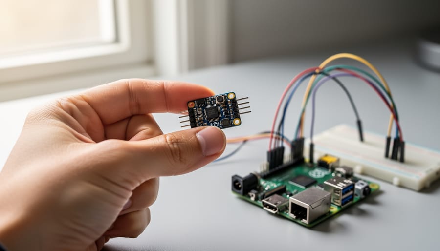
Working with electronics requires care, even on small projects. Before connecting your gyroscope sensor, power down your Raspberry Pi completely and unplug it from any power source. Static electricity can damage sensitive components, so touch a grounded metal object before handling the sensor or Pi to discharge any built-up charge. If you have an anti-static wrist strap, now’s the time to use it.
Check your sensor’s datasheet to confirm its voltage requirements. The vast majority of modern gyroscope modules designed for hobbyist use work at 3.3V logic levels, matching the Raspberry Pi’s GPIO output perfectly. However, some older sensors or industrial modules may require different voltages or level shifters as part of your hardware interface solutions.
Set up a clean, well-lit workspace with enough room to spread out your components. Gather your Raspberry Pi, gyroscope sensor, jumper wires, and breadboard where you can see the pin labels clearly. Poor lighting leads to misconnections, which cause frustrating troubleshooting sessions later.
Your sensor will communicate through the I2C protocol, a two-wire system that lets multiple devices share the same data lines. I2C is disabled by default on Raspberry Pi OS, so you’ll need to activate it before the sensor can work. Have your keyboard and monitor ready, or prepare for SSH access if you’re working headlessly. Verifying that I2C tools are installed now saves time once you start connecting wires.
Double-check that your power supply provides stable output, gyroscope sensors are sensitive to voltage fluctuations, which create noisy readings that make calibration difficult.
Understanding Your Gyroscope Sensor
A gyroscope sensor measures rotational motion, specifically, the rate at which an object rotates around its three axes (X, Y, and Z). Unlike accelerometers that detect linear motion and gravity, gyroscopes track angular velocity in degrees per second. When you tilt or spin your device, the sensor outputs numerical values representing how fast that rotation occurs along each axis. This data becomes essential for projects requiring orientation tracking, stabilization, or gesture detection.
Gyroscope vs. IMU Modules
You’ll encounter two main categories when shopping for compatible sensors. Gyroscope-only modules like the L3GD20 provide pure rotational data, making them simpler and often cheaper. IMU (Inertial Measurement Unit) modules combine a gyroscope with an accelerometer, and sometimes a magnetometer, into one package. The popular MPU-6050 exemplifies this approach, giving you both linear and rotational motion sensing. For most Raspberry Pi projects, IMUs offer better value since combining gyroscope and accelerometer data produces more accurate orientation tracking through sensor fusion algorithms.
Common Sensor Types in 2026
The MPU-6050 remains widely available and well-documented, though newer options like the ICM-20948 and LSM6DS3 offer improved accuracy and lower power consumption. Expect 3-axis gyroscopes as standard, with measurement ranges typically between 250 and 2000 degrees per second. Budget modules cost $3-8, while precision sensors for demanding applications run $15-25.
Identifying Your Pin Configuration
Most gyroscope modules expose 4-8 pins along one edge. Look for labels printed on the PCB. The essential connections are VCC (power), GND (ground), SDA (data), and SCL (clock), these four handle I2C communication. Some modules include additional pins like INT (interrupt), AD0 (address select), or XDA/XCL (auxiliary I2C). Check your module’s datasheet or product listing to confirm which pins you’ll actually use, as layouts vary between manufacturers even for the same sensor chip.
Step-by-Step: Connecting the Gyroscope to Raspberry Pi
Step 1: Enable I2C on Your Raspberry Pi
Before connecting your gyroscope sensor, you need to activate the I2C protocol on your Raspberry Pi. This communication interface is disabled by default but is essential for the sensor to transmit data.
Open a terminal and type:
“`
sudo raspi-config
“`
Navigate to Interfacing Options (or Interface Options on newer Raspberry Pi OS versions), then select I2C. Choose Yes when asked if you want to enable the I2C interface. Exit the configuration tool and reboot your Pi with `sudo reboot`.
After rebooting, install the I2C tools package:
“`
sudo apt-get update
sudo apt-get install i2c-tools
“`
Now verify that I2C is active by running:
“`
i2cdetect -y 1
“`
You should see a grid displaying available I2C addresses. If the command executes without errors and shows the grid (even if empty for now), I2C is successfully enabled. The number “1” refers to the I2C bus on newer Raspberry Pi models. If you’re using an original Model A or B, use `i2cdetect -y 0` instead.
Step 2: Wire the Sensor to GPIO Pins
With the I2C interface enabled, you’re ready to make the physical connections between your gyroscope sensor and Raspberry Pi. This step requires careful attention to pin placement, incorrect wiring can damage your sensor or prevent it from working.
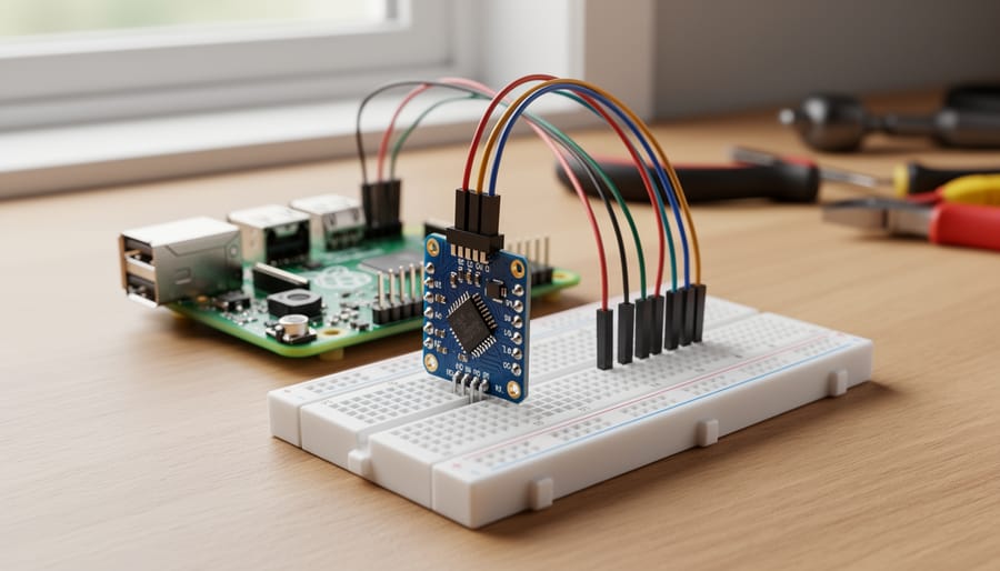
Locate the GPIO header on your Raspberry Pi. You’ll be using four specific pins for this connection. First, connect the sensor’s VCC pin to physical pin 1 (3.3V power) on the GPIO header using a red jumper wire. Most MPU-6050 and similar gyroscope modules operate at 3.3V, though some accept 5V, check your sensor’s specifications before connecting power.
Next, connect the sensor’s GND pin to physical pin 6 (ground) using a black wire. Ground provides the reference voltage for all signals and completes the power circuit.
For data communication, connect the sensor’s SDA pin to physical pin 3 (GPIO 2) using a blue or green wire. This is the I2C data line where information flows bidirectionally between the Pi and sensor. Finally, connect the sensor’s SCL pin to physical pin 5 (GPIO 3) using a yellow or white wire, this carries the I2C clock signal that synchronizes data transmission.
If your sensor module has additional pins labeled INT, AD0, or XDA, leave them unconnected for basic operation. Double-check each connection matches the pin numbers exactly. Physical pins are numbered sequentially along the header edge, different from GPIO numbering. A single misplaced wire can prevent detection or cause erratic behavior.
Step 3: Verify the Connection
With your sensor physically connected, you need to confirm the Raspberry Pi can communicate with it before writing any code. Open a terminal and run:
“`
i2cdetect -y 1
“`
This command scans the I2C bus and displays a grid showing all detected devices. If your gyroscope is properly connected, you’ll see a two-digit hexadecimal number, typically `68` or `69`, in the grid. The MPU-6050, for example, usually appears at address 0x68. If the AD0 pin on your sensor is pulled high, it shifts to 0x69.
If you see `–` where your sensor should be, double-check your wiring. Verify SDA connects to GPIO 2 (pin 3) and SCL to GPIO 3 (pin 5). Make sure VCC and GND connections are secure and providing power to the sensor.
On older Raspberry Pi models (like the original Model B), use `-y 0` instead of `-y 1` to scan bus 0 rather than bus 1.
If the sensor still doesn’t appear, try testing with a different set of jumper wires, loose connections are the most common culprit at this stage.
Step 4: Install Required Python Libraries
With your sensor successfully detected on the I2C bus, you need Python libraries to communicate with it and interpret its data. The specific libraries depend on your gyroscope module, but most builds use either SMBus for direct register access or higher-level libraries like Adafruit CircuitPython.
Start by updating your package manager and installing pip if it’s not already available:
“`
sudo apt update
sudo apt install python3-pip python3-venv
“`
For MPU-6050 or similar sensors, install the SMBus library:
“`
sudo pip3 install smbus2
“`
If you’re using Adafruit breakout boards like the L3GD20 or LSM6DS33, install their CircuitPython library:
“`
sudo pip3 install adafruit-circuitpython-l3gd20
“`
Alternatively, create a virtual environment to isolate project dependencies, this prevents library conflicts across different projects:
“`
python3 -m venv ~/gyro-project
source ~/gyro-project/bin/activate
pip install smbus2
“`
Check your sensor’s datasheet or manufacturer documentation to confirm which library it requires. Some sensors work with generic I2C libraries, while others need manufacturer-specific packages that handle calibration and data conversion automatically.
Step 5: Write the Python Code to Read Sensor Data
“`python
import smbus
import time
bus = smbus.SMBus(1)
device_address = 0x68
bus.write_byte_data(device_address, 0x6B, 0)
def read_gyro_data():
gyro_x = bus.read_byte_data(device_address, 0x43) << 8 | bus.read_byte_data(device_address, 0x44)
gyro_y = bus.read_byte_data(device_address, 0x45) << 8 | bus.read_byte_data(device_address, 0x46)
gyro_z = bus.read_byte_data(device_address, 0x47) << 8 | bus.read_byte_data(device_address, 0x48)
if gyro_x >= 0x8000:
gyro_x = -((65535 – gyro_x) + 1)
if gyro_y >= 0x8000:
gyro_y = -((65535 – gyro_y) + 1)
if gyro_z >= 0x8000:
gyro_z = -((65535 – gyro_z) + 1)
gyro_x = gyro_x / 131.0
gyro_y = gyro_y / 131.0
gyro_z = gyro_z / 131.0
return gyro_x, gyro_y, gyro_z
while True:
x, y, z = read_gyro_data()
print(f”Gyro X: {x:6.2f}°/s Y: {y:6.2f}°/s Z: {z:6.2f}°/s”)
time.sleep(0.5)
“`
This script establishes communication through the I2C bus and wakes the sensor from its default sleep state. The read_gyro_data function fetches raw 16-bit values from the gyroscope’s hardware registers, converts them to signed integers (handling negative rotations), then divides by 131 to translate the raw data into meaningful angular velocity measurements in degrees per second. The continuous loop displays real-time rotation rates around each axis, updating twice per second.
Step 6: Run and Test Your Script
Save your Python script as `gyro_test.py` and run it from the terminal with `python3 gyro_test.py`. You should see three columns of numbers streaming to your screen, representing rotation rates around the X, Y, and Z axes in degrees per second.
When the sensor sits still on your desk, expect values close to zero, typically between -2 and +2. Now physically rotate the sensor in different directions. Twist it left and right to see Z-axis values change. Tilt it forward and back to affect the Y-axis. Roll it side-to-side to move X-axis readings. Each movement should produce corresponding spikes in the relevant axis, confirming your sensor responds correctly to motion.
Press Ctrl+C to stop the script when you’re satisfied with the results.
Step 7: Calibrate and Optimize Sensor Readings
Raw gyroscope data rarely delivers pristine readings straight out of the box. You’ll notice the sensor reports small angular velocities even when sitting perfectly still, that’s zero-point drift, caused by temperature fluctuations and manufacturing tolerances.
To calibrate drift, collect 100-200 readings while the sensor remains motionless, then calculate the average for each axis. Subtract these offset values from all future readings. Run this calibration routine each time your program starts, since drift changes with temperature.
Noise appears as rapid fluctuations in your data. A simple low-pass filter smooths these spikes: multiply each new reading by 0.2, then add 0.8 times the previous reading. This weighted average preserves genuine movement while dampening electrical noise. Adjust the 0.2 factor higher for faster response or lower for smoother output.
Sampling rate matters for different applications. Motion tracking needs 50-100Hz updates, while slow orientation changes work fine at 10-20Hz. Set your reading interval using `time.sleep()` between measurements, shorter delays mean higher rates but increased CPU load.
Store your calibration offsets in a JSON file so you don’t recalibrate unnecessarily between sessions.
Verifying Your Setup Works Correctly
After running your Python script, you need to verify the gyroscope is reporting accurate data. Start by keeping the sensor completely still on a flat surface, you should see values close to zero on all three axes (X, Y, Z). Small fluctuations of ±5 degrees per second are normal due to sensor noise, but readings consistently higher than ±10 deg/s while stationary indicate a problem.
Now perform deliberate test movements. Rotate the sensor slowly around each axis one at a time and watch the corresponding values spike. For example, rotating clockwise around the Z-axis should produce positive values on that axis while X and Y remain near zero. Most hobby-grade gyroscopes like the MPU-6050 have a default range of ±250 deg/s, though some can be configured up to ±2000 deg/s for faster movements. Your readings during moderate hand rotations should fall between 50-200 deg/s, anything maxing out the range constantly suggests incorrect sensitivity settings.
Use this checklist to confirm everything is functioning properly:
- All three axes show near-zero values (within ±10 deg/s) when stationary
- Rotating the sensor produces clear, proportional changes on the correct axis
- Values return to near-zero after movement stops within 1-2 seconds
- No axis is stuck at maximum range values or flatlined at zero during movement
- Script runs without Python errors and updates continuously at your set sampling rate
If readings seem inverted (positive when you expect negative), that’s usually a mounting orientation issue rather than a malfunction. You can either physically reorient the sensor or multiply those axis values by -1 in your code. Erratic jumping between extreme values typically points to loose wiring or I2C communication errors, check your connections and verify the I2C address hasn’t changed.
Common Issues and Troubleshooting
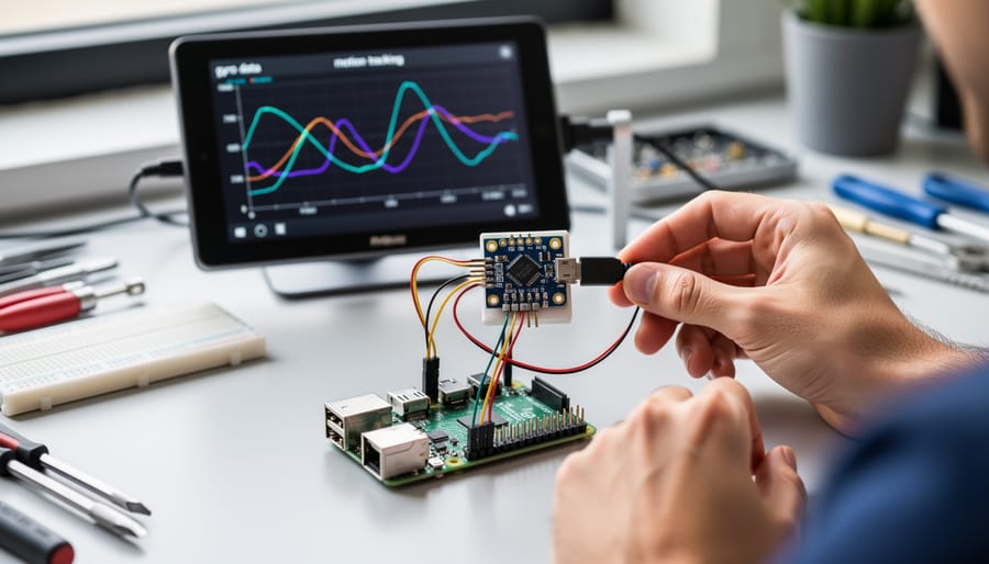
When you encounter problems with your gyroscope sensor, systematic troubleshooting saves time and frustration. Most issues fall into predictable categories with straightforward fixes.
Sensor Not Detected on I2C Bus
If `i2cdetect -y 1` shows no device at address 0x68 or 0x69, first verify your physical connections. A loose wire on SDA or SCL is the most common culprit. Check that you’ve connected to the correct GPIO pins, SDA to GPIO 2 and SCL to GPIO 3. Confirm I2C is actually enabled by running `sudo raspi-config` and navigating to Interface Options. Some sensors require you to bridge the AD0 pin to change the I2C address; check your module’s documentation if you’re certain the wiring is correct.
Erratic or Frozen Readings
When sensor values don’t change despite movement or show wild fluctuations, you’re likely facing a power problem. Gyroscope sensors are sensitive to voltage drops. If you’re powering multiple devices from your Pi’s 3.3V rail, try using a separate regulated power supply for the sensor. Poor-quality jumper wires can introduce resistance that causes voltage instability, swap them out for shorter, higher-quality wires. Adding a 0.1µF ceramic capacitor between VCC and GND on the sensor board can stabilize the power supply and eliminate noise.
Library and Code Errors
Python errors like `ModuleNotFoundError` or `ImportError` mean your required libraries aren’t installed in the active environment. Confirm you’re using the correct Python version (check with `python3 –version`) and reinstall packages with `pip3 install –upgrade smbus2`. Permission errors when accessing I2C typically require adding your user to the i2c group: `sudo usermod -a -G i2c pi`, followed by a logout and login.
Why does my sensor work intermittently?
Intermittent operation usually indicates a loose connection or insufficient power. Re-seat all jumper wires firmly and ensure your power supply provides stable voltage under load.
What does “Remote I/O error” mean?
This error indicates the Pi cannot communicate with the sensor over I2C. Check your wiring, verify the correct I2C address, and confirm the sensor isn’t damaged by testing with another module if available.
Can I connect multiple gyroscopes to one Raspberry Pi?
Yes, but each must have a unique I2C address. Most modules let you change the address by connecting the AD0 pin to VCC or GND, giving you two possible addresses per sensor type.
I2C Address Conflicts
If you’ve connected multiple I2C devices and your gyroscope stops working, run `i2cdetect -y 1` to see what addresses are occupied. Two devices sharing the same address will conflict. Change one device’s address using its address selection pin, or use an I2C multiplexer to manage multiple sensors on separate channels. The TCA9548A multiplexer is a reliable choice for expanding I2C capacity.
When troubleshooting, change one variable at a time and test after each modification. This methodical approach helps you identify exactly what fixed the problem, building your understanding for future projects.
Next Steps and Project Ideas

With your gyroscope integrated and tested, you’re ready to tackle more sophisticated projects. The real power emerges when you combine multiple sensors to capture richer movement data.
Pairing your gyroscope with an accelerometer (both often included in IMU modules like the MPU-6050) enables full 6-axis motion tracking. This combination compensates for each sensor’s weaknesses, accelerometers measure linear movement but drift during rotation, while gyroscopes track angular velocity but struggle with steady-state positioning. Together, they create robust orientation tracking through complementary filtering or Kalman filtering algorithms. This fusion forms the foundation for gesture recognition systems that respond to hand movements, arm tilts, or device shakes.
For robotics applications, gyroscope data becomes essential for balancing algorithms in self-balancing robots or two-wheeled platforms. The sensor feeds real-time tilt angles to your control loop, letting the robot correct its posture milliseconds before tipping. Quadcopter and drone builders use gyroscope readings for stabilization, detecting unwanted rotation on pitch, roll, and yaw axes so flight controllers can adjust motor speeds and maintain level flight.
If you want visual feedback during development, you can build a GUI that displays live sensor values or 3D orientation visualization. For portable motion-sensing projects, adding Raspberry Pi Zero WiFi lets you stream sensor data wirelessly to other devices or cloud dashboards.
Advanced developers interested in real-time performance can explore baremetal sensor work that bypasses the operating system for deterministic timing. The integration you’ve built serves as a launchpad, motion-controlled interfaces, navigation systems, and activity trackers all start with the same sensor foundation you’ve now mastered.