

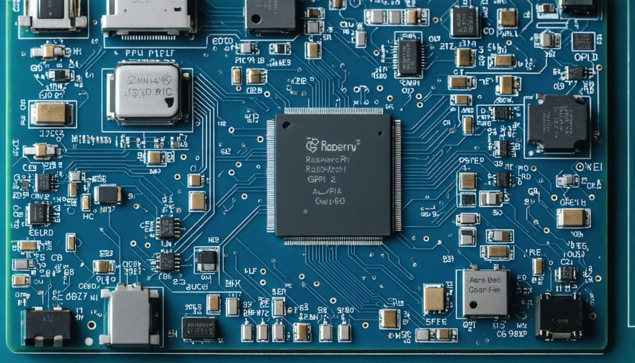
Dive into bare metal programming on Raspberry Pi to unlock unprecedented control and performance capabilities that surpass traditional operating systems. By directly accessing hardware registers and implementing custom bootloaders, developers can create ultra-efficient applications that execute with minimal overhead and maximum speed. While optimizing Raspberry Pi performance through conventional means yields modest gains, bare metal programming eliminates operating system constraints entirely, enabling microsecond-precise timing and complete hardware resource management.
This direct hardware manipulation opens doors to real-time applications, custom embedded systems, and educational platforms that demonstrate fundamental computer architecture principles. Whether you’re building a specialized IoT device, developing time-critical control systems, or simply exploring the depths of computer engineering, bare metal programming on Raspberry Pi provides the ultimate platform for understanding and controlling computer hardware at its most fundamental level.
The journey from high-level applications to bare metal programming challenges conventional programming paradigms, but rewards developers with unparalleled system control and performance optimization possibilities. This comprehensive guide will walk you through the essential concepts, tools, and techniques needed to master bare metal development on the Raspberry Pi platform.
Direct Hardware Access: Understanding the Basics
ARM Architecture Fundamentals
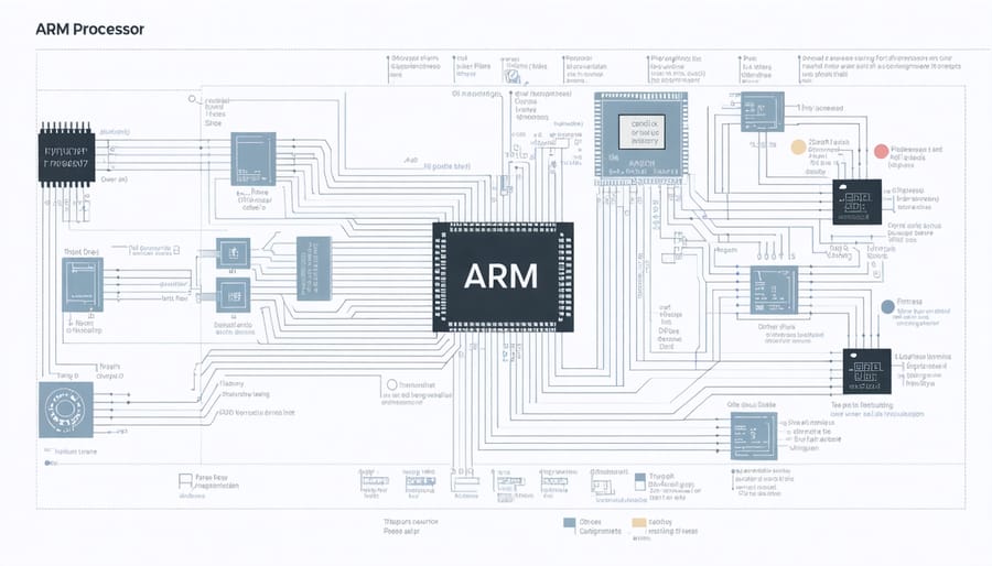
The ARM architecture, which powers the Raspberry Pi, provides a solid foundation for baremetal programming. Understanding its fundamentals is crucial for effective system architecture optimization and low-level development. At its core, ARM uses a load-store architecture, meaning data must be loaded into registers before processing and stored back to memory afterward.
The Raspberry Pi’s ARM processor features 16 general-purpose registers (R0-R15), with some having special functions. R13 serves as the stack pointer (SP), R14 as the link register (LR), and R15 as the program counter (PC). This register-based design enables efficient data manipulation and program execution.
ARM processors operate in different privilege levels, with the most privileged being the exception level (EL). In baremetal programming, you’ll typically work at EL1, which gives you direct hardware access. The processor also supports different execution states: ARM (32-bit) and Thumb (16-bit), offering flexibility in code density and performance.
Understanding these architectural elements is essential for writing efficient baremetal code and managing hardware resources effectively.
Memory Mapping and Registers
In bare metal programming on the Raspberry Pi, memory mapping is your direct line of communication with the hardware. The Pi’s peripherals are accessed through specific memory addresses, where each register corresponds to a particular hardware function. For example, to control the GPIO pins, you’ll need to access the base address 0x3F200000 (on Pi 3) or 0xFE200000 (on Pi 4).
To interact with these registers, you’ll typically create pointer variables that map to these memory locations. This is done using volatile pointers to ensure the compiler doesn’t optimize away your hardware accesses. Here’s what you need to know:
– Physical memory must be mapped to virtual memory using a memory management unit (MMU)
– Registers are typically 32-bit values that control specific hardware functions
– Memory barriers are essential when accessing hardware to ensure proper synchronization
– Different peripheral registers require different access patterns (read-only, write-only, or read-write)
Understanding the memory map is crucial for tasks like configuring GPIO pins, setting up timers, or managing interrupts. Always consult the Raspberry Pi’s official documentation for the correct memory addresses and register definitions for your specific model.
Setting Up Your Development Environment
Required Tools and Compilers
To begin your bare metal Raspberry Pi journey, you’ll need several essential tools and compilers for effective development. The most crucial component is the GNU Arm Embedded Toolchain, which includes the gcc-arm-none-eabi compiler specifically designed for ARM architecture. This toolchain is fundamental for custom OS development and bare metal programming.
You’ll also need a reliable text editor or IDE. Popular choices include Visual Studio Code with the Cortex-Debug extension, or Eclipse with the GNU MCU plugin. These provide helpful features like syntax highlighting and debugging capabilities.
For debugging and hardware interaction, install OpenOCD (On-Chip Debugger) and QEMU for ARM. OpenOCD helps interface with your Raspberry Pi’s hardware, while QEMU allows you to test your code in an emulated environment before deploying it to actual hardware.
Make sure to download the official Raspberry Pi firmware files and bootloader, which contain essential binary blobs and boot code. You’ll find these in the Raspberry Pi GitHub repository.
Finally, install a build system like Make or CMake to automate your compilation process. These tools help manage dependencies and streamline your development workflow, making it easier to focus on writing code rather than dealing with compilation details.

Configuring the Build System
To build our baremetal Raspberry Pi project, we’ll need to set up a proper build system using a Makefile. This essential tool will automate our compilation process and manage dependencies effectively.
Create a Makefile in your project’s root directory with the following basic structure:
“`makefile
ARMGNU = arm-none-eabi
CFLAGS = -O2 -Wall -nostdlib -nostartfiles -ffreestanding
all: kernel.img
kernel.img: kernel.o
$(ARMGNU)-ld -T linker.ld -o kernel.elf kernel.o
$(ARMGNU)-objcopy kernel.elf -O binary kernel.img
kernel.o: kernel.c
$(ARMGNU)-gcc $(CFLAGS) -c kernel.c -o kernel.o
clean:
rm -f *.o *.elf *.img
“`
This Makefile specifies the ARM GNU toolchain we’ll use, sets important compiler flags, and defines the build process. The -nostdlib and -ffreestanding flags are crucial as they indicate we’re working without standard libraries in a freestanding environment.
Remember to adjust the compiler flags based on your specific Raspberry Pi model and requirements. For debugging purposes, you might want to add -g flag to include debugging information.
To compile your project, simply run ‘make’ in the terminal. The build system will generate a kernel.img file, which is the binary that your Raspberry Pi will execute.
Writing Your First Baremetal Program
Boot Code Implementation
The boot code implementation is a crucial first step in bare metal programming for the Raspberry Pi. This code executes immediately when the processor starts up and sets up the essential hardware environment. At its core, we need to create a vector table that handles various processor exceptions and interrupts.
Start by creating a file named “boot.S” in your project directory. This assembly file will contain the initial entry point and vector table setup. The first instruction must be located at memory address 0x8000, which is where the Raspberry Pi’s GPU loads our code.
Here’s a basic implementation:
“`asm
.section .text.boot
.global _start
_start:
// Disable all cores except CPU 0
mrc p15, 0, r1, c0, c0, 5
and r1, r1, #3
cmp r1, #0
bne halt
// Set up the stack pointer
ldr r1, =_start
mov sp, r1
// Clear the BSS section
ldr r4, =__bss_start
ldr r9, =__bss_end
mov r5, #0
mov r6, #0
“`
This code ensures only one core runs our program, sets up the stack pointer, and initializes the BSS section. After this basic setup, we can branch to our main C function where the bulk of our program will run.
Remember to link this file correctly in your build system and ensure it’s placed at the correct memory address. The linker script plays a crucial role in positioning this code correctly in memory.
GPIO Control Example
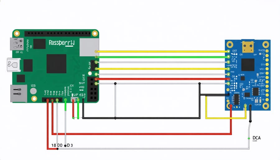
Let’s explore a practical example of GPIO control by creating a simple LED blinking program. We’ll directly manipulate the GPIO registers to toggle an LED connected to GPIO pin 16.
First, we need to set up the GPIO function select register (GPFSEL1) to configure pin 16 as an output:
“`c
volatile unsigned int* GPFSEL1 = (unsigned int*)0x20200004;
*GPFSEL1 &= ~(7 << 18); // Clear bits
*GPFSEL1 |= (1 << 18); // Set as output
```
To control the LED state, we'll use the GPIO Set (GPSET0) and Clear (GPCLR0) registers:
```c
volatile unsigned int* GPSET0 = (unsigned int*)0x2020001C;
volatile unsigned int* GPCLR0 = (unsigned int*)0x20200028;
// Turn LED on
*GPSET0 = 1 << 16;
// Turn LED off
*GPCLR0 = 1 << 16;
```
To create a blinking effect, we can implement a simple delay function using a loop:
```c
void delay(int count) {
for (volatile int i = 0; i < count; i++);
}
// Main loop
while(1) {
*GPSET0 = 1 << 16; // LED on
delay(500000);
*GPCLR0 = 1 << 16; // LED off
delay(500000);
}
```
This basic example demonstrates direct hardware manipulation without relying on operating system functions or libraries. Remember to connect your LED with an appropriate current-limiting resistor to prevent damage to the component or your Raspberry Pi.
Advanced Hardware Integration
Timer and Interrupt Handling
Timer management and interrupt handling are crucial aspects of bare-metal Raspberry Pi programming. The BCM2835/BCM2836 chips provide several hardware timers that you can utilize for precise timing operations. The system timer, which runs at 1MHz, offers four comparison registers (timer channels 0-3), with channels 1 and 3 typically available for custom use.
To set up a timer, you’ll need to access the system timer’s base address and configure the appropriate comparison registers. Here’s a basic example:
“`c
volatile unsigned int* TIMER_BASE = (unsigned int*)0x20003000;
TIMER_BASE[4] = TIMER_BASE[1] + 1000000; // Set timer to trigger in 1 second
“`
The interrupt controller is essential for handling timer events and other hardware interrupts. The Raspberry Pi features two types of interrupt controllers: the legacy ARM interrupt controller and the local interrupt controller (on multi-core models). To enable interrupts, you must:
1. Configure the interrupt controller
2. Set up interrupt service routines (ISRs)
3. Enable specific interrupt sources
4. Enable global interrupts
Remember to handle interrupts efficiently and keep ISRs as short as possible. Long-running interrupt handlers can cause system instability and affect real-time performance. Always clear interrupt flags after handling to prevent repeated triggering.
UART Communication
UART (Universal Asynchronous Receiver/Transmitter) is one of the fundamental hardware communication protocols you’ll need to master for baremetal programming. On the Raspberry Pi, UART provides a reliable way to communicate with external devices and debug your code without operating system support.
To implement UART communication, you’ll need to configure the GPIO pins 14 (TX) and 15 (RX). Start by setting up the UART registers: initialize the baud rate by writing to the UART_IBRD and UART_FBRD registers, enable the FIFO, and set the line control register for 8-bit data transmission.
Here’s a basic initialization sequence:
1. Disable the UART
2. Set the baud rate divisor
3. Configure the line control register
4. Enable the UART
5. Enable the TX and RX functions
For sending data, write to the UART data register (UART_DR) after checking the transmit FIFO is not full. For receiving, read from the same register when data is available. Remember to implement proper handshaking to prevent data loss.
A simple way to test your UART implementation is by connecting a USB-to-TTL converter and using a terminal program on your computer to send and receive messages.
Embarking on baremetal programming for Raspberry Pi presents both exciting opportunities and notable challenges. The direct hardware access allows for unprecedented control over the system, resulting in highly efficient and specialized applications. Developers can achieve faster execution times, reduced memory overhead, and precise timing control – benefits that are particularly valuable in real-time applications and embedded systems.
However, this journey requires dedication and patience. Without the abstraction layers provided by an operating system, programmers must handle every hardware interaction manually, from GPIO management to memory allocation. This complexity demands a deeper understanding of computer architecture and hardware principles, making the learning curve steeper than traditional application development.
Despite these challenges, the rewards of baremetal programming are substantial. The skills acquired through this process provide invaluable insights into computer systems, making you a more capable developer overall. The Raspberry Pi’s accessible hardware and extensive community support make it an ideal platform for exploring these concepts.
For those considering baremetal development, start with simple projects like LED control or basic I/O operations before progressing to more complex applications. The community resources, documentation, and example projects available online can significantly ease the learning process. While the path may be challenging, the ability to create highly optimized, purpose-built applications makes baremetal programming on Raspberry Pi a worthwhile endeavor for dedicated developers and hobbyists alike.