


Master Arduino-powered 6-axis robot arms through systematic code implementation that transforms complex robotics into manageable steps. Whether you’re new to building Arduino robots or advancing your skills, proper code architecture ensures precise control over each servo motor and smooth coordination across all axes. This guide breaks down essential programming concepts, from basic joint movement to advanced inverse kinematics, enabling you to create sophisticated robotic movements with Arduino’s versatile platform.
Starting with fundamental servo control libraries and progressing to comprehensive motion planning algorithms, you’ll learn to implement professional-grade solutions that address common challenges in robotic arm programming. Our step-by-step approach covers servo calibration, coordinate system transformation, and real-time position feedback – critical elements for achieving reliable and accurate robotic manipulation.
By focusing on modular code structure and efficient memory management, this tutorial ensures your robot arm project remains scalable and maintainable. Whether you’re building a desktop-sized arm for education or developing a larger prototype for industrial applications, these code examples and implementation strategies provide a solid foundation for success.
Hardware Requirements and Setup
Required Components
To build a 6-axis robot arm with Arduino, you’ll need the following essential components:
1. Arduino Board
– Arduino Mega 2560 (recommended for multiple servo control)
– USB cable for programming
2. Servo Motors
– 6x MG996R servo motors (or similar high-torque servos)
– Ensure each servo has at least 10kg/cm torque
– Metal gears recommended for durability
3. Power Supply
– 6-12V DC power supply
– Minimum 2A current output
– Separate power source for servos recommended
4. Structural Components
– Robot arm frame (3D printed or purchased kit)
– Servo brackets and mounting hardware
– Base plate for stability
– End effector (gripper or tool mount)
5. Electronic Components
– Breadboard for prototyping
– Jumper wires (male-to-male, female-to-female)
– Capacitors (100μF) for servo power smoothing
– Power distribution board or terminal blocks
6. Optional Components
– Servo signal multiplexer
– Potentiometers for manual control
– LCD display for status monitoring
– Emergency stop button
– Limit switches for safety
Remember to verify the compatibility of all components before assembly and ensure your power supply can handle the combined current draw of all servos under load.
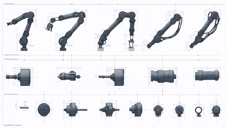
Assembly Guidelines
Begin by mounting the base servo motor to your chosen platform using the provided mounting brackets and screws. Ensure it’s firmly secured as this forms the foundation of your robot arm. Next, attach the waist component to the base servo’s shaft using the servo horn and corresponding hardware.
Proceed to assemble the shoulder joint by connecting the second servo motor to the waist assembly. Double-check that all wiring has enough slack for full rotation while remaining organized. The elbow joint comes next – mount the third servo and attach the corresponding arm segment, maintaining proper alignment.
For the wrist assembly, carefully connect the fourth and fifth servo motors in a perpendicular configuration to enable both pitch and roll movements. The final servo motor mounts at the end for the gripper rotation. When attaching the gripper mechanism, ensure smooth operation without binding.
Connect all servo motors to your Arduino board following your chosen pin configuration. Use a separate power supply for the servos to prevent overloading the Arduino. Bundle wires neatly using zip ties or cable management solutions, leaving enough slack for full range of motion.
Finally, test each joint individually before attempting full arm movements. This methodical approach helps identify any mechanical issues early in the assembly process. Remember to calibrate each servo to its center position before proceeding with programming.
Understanding Servo Control Basics
Servo Library Implementation
The Arduino Servo library is essential for controlling the servos in your 6-axis robot arm. Start by including the library at the top of your code with #include
Initialize each servo using the attach() function in your setup() block, specifying the correct Arduino pins. For precise control, utilize the write() function, which accepts values between 0 and 180 degrees. When working with continuous rotation servos, use writeMicroseconds() instead, with values ranging from 1000 to 2000.
To prevent jerky movements, implement gradual position changes by creating small increments between current and target positions. Consider using the read() function to track current servo positions and implement position limits to protect your robot arm from mechanical stress. Remember to include small delays between movements to allow servos to reach their intended positions.
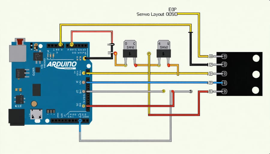
Basic Movement Functions
To control a 6-axis robot arm with Arduino, you’ll need to create several fundamental movement functions that handle individual servo operations. Start by defining functions for each axis using the Servo library:
“`cpp
void moveBase(int angle) {
baseServo.write(angle);
delay(15);
}
void moveShoulder(int angle) {
shoulderServo.write(angle);
delay(15);
}
void moveElbow(int angle) {
elbowServo.write(angle);
delay(15);
}
“`
Create a comprehensive movement function that combines individual axis controls:
“`cpp
void moveToPosition(int base, int shoulder, int elbow, int wrist, int rotation, int gripper) {
baseServo.write(base);
shoulderServo.write(shoulder);
elbowServo.write(elbow);
wristServo.write(wrist);
rotationServo.write(rotation);
gripperServo.write(gripper);
delay(1000);
}
“`
For smooth movements, implement acceleration control:
“`cpp
void smoothMove(int startAngle, int endAngle, Servo &servo) {
int step = (startAngle < endAngle) ? 1 : -1;
for (int angle = startAngle; angle != endAngle; angle += step) {
servo.write(angle);
delay(15);
}
}
```
These basic functions form the foundation for more complex movements and sequences. Remember to include appropriate delay times between movements to prevent servo strain and ensure smooth operation.
Core Arduino Code Implementation
Variable Declarations and Setup
Before diving into the main program, we need to set up our essential variables and libraries for controlling the 6-axis robot arm. Start by including the Servo library, which will handle the individual motor control:
#include
// Create servo objects for each axis
Servo base; // Base rotation
Servo shoulder; // Shoulder joint
Servo elbow; // Elbow joint
Servo wrist; // Wrist pitch
Servo wristRoll; // Wrist roll
Servo gripper; // End effector
// Define Arduino pins for each servo
const int basePin = 3;
const int shoulderPin = 5;
const int elbowPin = 6;
const int wristPin = 9;
const int wristRollPin = 10;
const int gripperPin = 11;
// Initialize position variables
int basePos = 90; // Starting position for base
int shoulderPos = 90; // Starting position for shoulder
int elbowPos = 90; // Starting position for elbow
int wristPos = 90; // Starting position for wrist
int wristRollPos = 90;// Starting position for wrist roll
int gripperPos = 90; // Starting position for gripper
// Define movement limits
const int minAngle = 0;
const int maxAngle = 180;
const int moveSpeed = 15; // Delay between movements in milliseconds
These variables provide the foundation for controlling each axis of the robot arm while maintaining safe operating parameters.
Movement Control Functions
The movement control functions form the core of your 6-axis robot arm’s operation. Here’s a basic implementation of the essential movement functions:
“`cpp
void moveServo(int servoIndex, int targetAngle) {
int currentAngle = currentPositions[servoIndex];
while (currentAngle != targetAngle) {
if (currentAngle < targetAngle) currentAngle++;
else currentAngle--;
servos[servoIndex].write(currentAngle);
currentPositions[servoIndex] = currentAngle;
delay(15);
}
}
void moveToPosition(int angles[6]) {
for (int i = 0; i < 6; i++) {
moveServo(i, angles[i]);
}
}
void homePosition() {
int homeAngles[6] = {90, 90, 90, 90, 90, 90};
moveToPosition(homeAngles);
}
void gripperControl(bool open) {
if (open) {
servos[5].write(180); // Open position
} else {
servos[5].write(0); // Closed position
}
currentPositions[5] = servos[5].read();
}
```
These functions handle individual servo movement, coordinated movement of all axes, returning to home position, and gripper control. The moveServo function includes speed control through delays, ensuring smooth movement and reducing servo strain. Remember to adjust delay values based on your specific servo motors and application requirements.
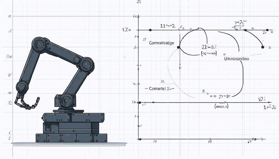
Inverse Kinematics Integration
Implementing inverse kinematics is crucial for precise control of your 6-axis robot arm. The calculations allow the arm to move to specific coordinates by automatically determining the required angles for each joint. Here’s how to integrate inverse kinematics into your Arduino code:
First, create a structure to store the target position and orientation:
“`cpp
struct Position {
float x, y, z; // Cartesian coordinates
float roll, pitch, yaw; // End effector orientation
};
“`
Next, implement the inverse kinematics function:
“`cpp
void calculateAngles(Position target, float &theta1, float &theta2, float &theta3,
float &theta4, float &theta5, float &theta6) {
// Base rotation
theta1 = atan2(target.y, target.x);
// Calculate arm angles using geometric approach
float r = sqrt(target.x*target.x + target.y*target.y);
float s = target.z – L1; // L1 is base height
// Additional calculations for remaining angles
theta2 = calculateTheta2(r, s);
theta3 = calculateTheta3(r, s);
// Wrist angles
theta4 = target.roll;
theta5 = target.pitch;
theta6 = target.yaw;
}
“`
To use these calculations in your main loop, simply call the function with your desired position:
“`cpp
Position targetPos = {200, 150, 100, 0, 0, 0};
float angles[6];
calculateAngles(targetPos, angles[0], angles[1], angles[2],
angles[3], angles[4], angles[5]);
“`
Remember to adjust the calculations based on your specific robot arm dimensions and joint configurations.
Advanced Features and Optimization
Position Memory Implementation
Position memory functionality allows your 6-axis robot arm to remember and replay specific movements, making it incredibly useful for repetitive tasks. To implement this feature, we’ll use the Arduino’s EEPROM to store servo positions.
First, include the EEPROM library at the top of your code:
“`cpp
#include
“`
Create arrays to store current and saved positions:
“`cpp
int currentPos[6];
int savedPositions[5][6]; // Stores up to 5 different positions
“`
To save a position, implement a function that writes the current servo angles to EEPROM:
“`cpp
void savePosition(int slot) {
int address = slot * 12; // Each position uses 12 bytes
for(int i = 0; i < 6; i++) {
EEPROM.write(address + (i * 2), currentPos[i]);
}
}
```
For position recall, create a function that reads from EEPROM and moves servos accordingly:
```cpp
void recallPosition(int slot) {
int address = slot * 12;
for(int i = 0; i < 6; i++) {
int pos = EEPROM.read(address + (i * 2));
servos[i].write(pos);
delay(15);
}
}
```
You can trigger these functions using buttons or serial commands. Remember that EEPROM has limited write cycles, so use position storage sparingly and consider implementing a write verification check for reliability.
Smooth Movement Algorithms
Implementing smooth movement in a 6-axis robot arm requires careful attention to acceleration and deceleration to prevent jerky motions that could damage the servos or compromise precision. The key lies in using interpolation algorithms that calculate intermediate positions between the start and end points.
One effective approach is to implement a linear interpolation (LERP) function that gradually transitions between positions. Here’s a basic implementation:
“`cpp
float lerp(float start, float end, float t) {
return start + (end – start) * t;
}
“`
To create even smoother movements, consider using ease-in and ease-out functions that simulate natural acceleration and deceleration. The following cubic easing function produces more organic movements:
“`cpp
float cubicEase(float t) {
return t * t * (3 – 2 * t);
}
“`
To optimize code efficiency and maintain smooth operation, implement a movement queue that processes position updates at regular intervals. This prevents buffer overflows and ensures consistent timing between movements.
Remember to include delay calculations based on the distance between positions and maximum servo speeds. A good practice is to adjust movement speed dynamically based on the angle difference between current and target positions, allowing for faster transitions during large movements while maintaining precision for smaller adjustments.
Error Handling and Safety Features
When working with a 6-axis robot arm, proper error handling and safety measures are crucial to prevent damage to the equipment and ensure user safety. Start by implementing safety features such as limit switches at each joint’s maximum range. Add these checks in your code:
“`cpp
if (limitSwitch.isPressed() || currentAngle > MAX_ANGLE) {
stopMotor();
Serial.println(“Error: Joint limit reached”);
return;
}
“`
Include emergency stop functionality that can be triggered either through software or a physical button:
“`cpp
void checkEmergencyStop() {
if (digitalRead(EMERGENCY_PIN) == HIGH) {
disableAllMotors();
setErrorState(true);
}
}
“`
Monitor motor current to detect stalls or obstacles:
“`cpp
if (motorCurrent > CURRENT_THRESHOLD) {
stopMovement();
Serial.println(“Warning: Excessive motor current detected”);
}
“`
Implement a watchdog timer to reset the system if the main program freezes:
“`cpp
wdt_enable(WDTO_2S); // 2-second timeout
wdt_reset(); // Reset timer in main loop
“`
Always include position validation before executing movements to prevent self-collision and workspace violations. These safety measures will help ensure reliable operation of your robot arm project.
Testing and Troubleshooting
When testing your 6-axis robot arm code, start by performing individual joint movements at low speeds to verify basic functionality. Check each servo’s response and ensure they move to the expected positions without interference or binding. Pay attention to any unusual sounds or vibrations that might indicate mechanical issues or microcontroller performance considerations.
Common issues you might encounter include jerky movements, servos not reaching their target positions, or unexpected behavior. If servos aren’t moving, verify your power supply can handle the current draw from multiple servos moving simultaneously. A typical troubleshooting checklist includes:
1. Double-check all wire connections and servo pins
2. Verify servo PWM signals using an oscilloscope if available
3. Confirm servo calibration values are within acceptable ranges
4. Monitor serial output for debugging messages
5. Test with reduced movement speeds to isolate timing issues
If your arm exhibits erratic behavior, try implementing delay() functions between movements or adjusting acceleration parameters. Memory-related problems often manifest as inconsistent movements; consider optimizing your code by reducing variable sizes or implementing more efficient algorithms.
For smooth operation, ensure your Arduino isn’t overwhelmed by processing demands. Consider using interrupt-driven servo control or implementing a task scheduler for complex sequences. Remember to maintain proper grounding and shield sensitive electronics from motor interference.
Building a 6-axis robot arm with Arduino opens up endless possibilities for automation and experimentation. Throughout this guide, we’ve covered essential aspects from basic servo control to implementing inverse kinematics. By following these steps and understanding the code structure, you can create a fully functional robotic arm that responds to precise commands and performs complex movements.
To expand your project further, consider adding features like position memory, custom movement sequences, or even computer vision integration. You might also explore different control interfaces, such as smartphone apps or gesture recognition systems. Remember to regularly calibrate your servos and maintain proper power management for optimal performance.
The robotics community is constantly evolving, and sharing your modifications or improvements can help others on their journey. Whether you’re using this arm for education, hobby projects, or industrial prototyping, the foundation provided here will serve as a solid starting point for your robotics adventures.