

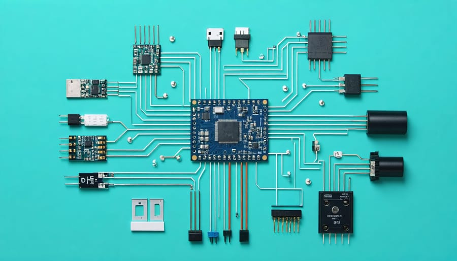
Master the elegance of 1-Wire communication protocol – a revolutionary single-bus system that connects multiple devices using just one data line and ground. Originally developed by Dallas Semiconductor, this ingenious protocol has become a cornerstone for getting started with Arduino projects, especially in temperature sensing and device identification applications.
Unlike complex multi-wire protocols, 1-Wire achieves bidirectional communication through a unique parasitic power arrangement, allowing devices to draw power directly from the data line. This clever design eliminates the need for separate power wiring, making it ideal for space-constrained projects and distributed sensor networks.
With transfer speeds ranging from standard 15.4 kbps to overdrive 125 kbps, 1-Wire delivers reliable performance while maintaining remarkable simplicity. Each device on the bus features a unique 64-bit ID, enabling precise addressing and error-free communication in networks with dozens of connected sensors, EEPROMs, or other peripheral devices.
Whether you’re building a home temperature monitoring system or creating a secure authentication mechanism, understanding 1-Wire opens up endless possibilities for elegant, efficient embedded system design. Let’s explore how this versatile protocol can transform your next project.
How 1-Wire Protocol Makes Arduino Communication Simple
Single-Wire Magic: The Basic Architecture
The 1-Wire protocol achieves its magic through a brilliantly simple architecture that requires just two connections: a single data wire and ground. This minimalist approach is possible thanks to an ingenious power arrangement called “parasitic power,” where devices can draw electricity directly from the data line when it’s in its idle (high) state.
When communication begins, the master device initiates by pulling the line low (0V) to signal the start of a transaction. Slave devices respond by either pulling the line low to transmit a ‘0’ or letting it float high to transmit a ‘1’. This bidirectional communication happens in precise time slots, with each bit transfer taking about 60 microseconds.
To prevent signal conflicts, 1-Wire uses a strict master-slave protocol where the master always controls the timing. Each slave device has a unique 64-bit ID, enabling the master to communicate with specific devices on the shared bus. This addressing system allows multiple sensors or devices to share the same wire while maintaining reliable individual communication.
The beauty of this design lies in its simplicity: fewer wires mean easier installation, reduced costs, and the ability to connect multiple devices over longer distances without additional complexity.

Master-Slave Communication Made Easy
In 1-Wire networks, communication follows a straightforward master-slave hierarchy. The master device, typically a microcontroller like Arduino or Raspberry Pi, initiates and controls all communication on the bus. Slave devices, such as temperature sensors or EEPROMs, respond only when addressed by the master.
The beauty of this arrangement lies in its simplicity. The master device starts each interaction with a reset pulse, followed by a ROM command to select a specific slave device. Each slave has a unique 64-bit ROM ID, ensuring precise communication even with multiple devices on the same bus.
Think of it like a teacher (master) in a classroom of students (slaves). The teacher calls on specific students by name, and only the addressed student responds. This prevents communication conflicts and ensures orderly data exchange.
The protocol handles timing automatically, with the master device maintaining the communication rhythm. Slave devices synchronize with this timing, making the entire process remarkably reliable. Even better, slaves can derive their power directly from the data line, reducing wiring complexity in your projects.
Setting Up Your First 1-Wire Network
Hardware Requirements
To implement 1-Wire communication, you’ll need just a few essential components. The primary requirement is a master device, typically a microcontroller like Arduino, Raspberry Pi, or any other compatible development board. The master device initiates and controls all communication on the bus.
You’ll also need one or more 1-Wire slave devices, such as temperature sensors (DS18B20), digital potentiometers, or memory chips. These devices are specifically designed to work with the 1-Wire protocol and come with unique 64-bit serial numbers for identification.
A pull-up resistor (typically 4.7kΩ) is crucial for proper operation. This resistor connects the data line to the power supply (usually 3.3V or 5V) and ensures reliable signal transmission. For the physical connection, you’ll need a single data wire, along with ground and power connections.
For longer cable runs (beyond 20 meters), consider using shielded cable to prevent interference. Some advanced implementations might also benefit from specialized 1-Wire hubs or network extenders, though these aren’t necessary for basic setups.
Wiring Your Circuit
To set up your 1-Wire communication network, you’ll need just a few basic components and a bit of careful wiring. Start by gathering a microcontroller (such as an Arduino or Raspberry Pi), your 1-Wire device(s), and a 4.7kΩ resistor for the pull-up resistor configuration.
Connect your microcontroller’s ground (GND) pin to the ground connection of your 1-Wire device. Next, connect the data pin (usually labeled DQ or DATA) of your 1-Wire device to a digital I/O pin on your microcontroller. This will be your communication line.
The power supply connection depends on whether you’re using parasitic power mode or external power mode:
For parasitic power:
– Connect the VDD pin of the 1-Wire device to ground
– Place the 4.7kΩ resistor between the data line and the microcontroller’s VCC (3.3V or 5V)
For external power:
– Connect the VDD pin to your microcontroller’s VCC
– Place the 4.7kΩ resistor between the data line and VCC
When connecting multiple 1-Wire devices, maintain the same ground connection for all devices. The data pins should all connect to the same microcontroller pin, creating a parallel configuration. Each device will still need its own connection to the power supply if using external power mode.
Remember to keep your wiring neat and avoid long cable runs, as this can affect signal integrity. For best results, try to keep the total bus length under 20 meters when using standard pull-up resistor values.
Programming Your Arduino
To get started with 1-Wire communication on your Arduino, you’ll need to include the OneWire library. Begin by installing it through the Arduino IDE’s Library Manager or downloading it directly from GitHub.
Here’s a basic example to read data from a 1-Wire device:
“`cpp
#include
// Initialize OneWire on pin 2
OneWire oneWire(2);
void setup() {
Serial.begin(9600);
}
void loop() {
byte addr[8];
// Search for 1-Wire devices
if (oneWire.search(addr)) {
Serial.print(“Device found: “);
for(int i = 0; i < 8; i++) {
Serial.print(addr[i], HEX);
Serial.print(" ");
}
Serial.println();
}
oneWire.reset_search();
delay(1000);
}
```
This code demonstrates device discovery on the 1-Wire bus. To communicate with specific devices, you'll need to implement the appropriate command sequences. For example, with a DS18B20 temperature sensor:
```cpp
oneWire.reset(); // Reset the bus
oneWire.select(addr); // Select the device
oneWire.write(0x44); // Start temperature conversion
delay(750); // Wait for conversion
```
Remember to include a 4.7kΩ pull-up resistor between your data line and VCC for reliable communication. The OneWire library handles the precise timing requirements, making it straightforward to implement 1-Wire communication in your projects.
Common 1-Wire Devices and Their Integration
Temperature Sensors (DS18B20)
The DS18B20 temperature sensor is one of the most popular implementations of the 1-Wire protocol, offering an excellent example of how this communication standard works in practice. This digital thermometer can measure temperatures from -55°C to +125°C with ±0.5°C accuracy, making it ideal for various projects.
Each DS18B20 comes with a unique 64-bit serial code, allowing multiple sensors to operate on the same 1-Wire bus. This feature demonstrates one of the protocol’s key advantages: the ability to connect multiple devices using just one data line.
To implement the DS18B20 in your project, you’ll need:
– A 4.7kΩ pull-up resistor between the data line and VDD
– Three wires: VDD (power), GND (ground), and DQ (data)
– Arduino or similar microcontroller
The sensor supports two power modes: external power (using VDD) or parasitic power (drawing power from the data line). In parasitic mode, you can run the sensor using just two wires, though external power is recommended for more reliable operation.
Communication begins with the microcontroller sending a reset pulse, followed by ROM commands to address specific sensors, and then temperature conversion commands. The sensor responds with 12-bit temperature readings, which can be easily converted to Celsius or Fahrenheit.
Other Popular 1-Wire Devices
While the DS18B20 temperature sensor is perhaps the most well-known 1-Wire device, the protocol supports a diverse range of useful components. The DS2408 offers eight channels of programmable I/O, making it perfect for controlling multiple LEDs, switches, or relays through a single wire. For memory applications, the DS2431 provides 1024 bits of non-volatile EEPROM storage, ideal for storing configuration data or small datasets.
Security-focused makers often turn to the DS1990A iButton, a unique serial number device housed in a durable stainless steel case that works great for electronic keys and access control systems. The DS2423 counter IC is popular in projects requiring pulse counting or event tracking, such as monitoring rainfall or tracking mechanical movements.
For precise timekeeping, the DS1904 RTC (Real-Time Clock) maintains accurate time even during power outages thanks to its built-in battery backup. The DS2438 smart battery monitor is particularly useful in portable projects, providing accurate measurements of battery voltage, current, and temperature.
These devices showcase the versatility of the 1-Wire protocol, allowing makers to create sophisticated projects while maintaining simple wiring schemes. Most of these components are readily available and can be easily integrated into Arduino or Raspberry Pi projects using standard 1-Wire libraries.
Troubleshooting Your 1-Wire Setup

Communication Issues
While 1-Wire is designed to be simple and reliable, several common issues can arise during implementation. The most frequent problem is signal degradation over long distances, particularly when cable lengths exceed 20 meters. To mitigate this, using proper pull-up resistors (typically 4.7kΩ) and high-quality cables with minimal interference is essential.
Timing issues are another significant challenge. The protocol requires precise timing for communication, and incorrect delays between read/write operations can lead to data corruption. When troubleshooting, ensure your code includes appropriate delay intervals between commands and verify that your microcontroller’s clock speed is accurately configured.
Parasitic power mode can be problematic, especially with multiple devices on the bus. If devices appear to respond intermittently, consider switching to external power mode or reducing the number of devices on the bus. Additionally, check for proper grounding and ensure all devices share a common ground connection.
Address collision is common when multiple devices are present on the bus. Implementing proper device enumeration and verification steps in your code can help avoid this issue. If devices aren’t responding, use a logic analyzer to verify the presence pulse and timing of communications.
For reliable operation in noisy environments, consider adding capacitors near devices for power supply filtering and using twisted-pair cables to reduce electromagnetic interference.
Hardware Problems
When implementing 1-Wire communication, several common hardware issues can arise, but most are easily solvable with the right approach. The most frequent problem is signal degradation over long distances. To combat this, use high-quality shielded cables and keep wire lengths under 20 meters for optimal performance. If longer distances are necessary, consider adding 1-Wire repeaters to boost signal strength.
Pull-up resistor configuration is another critical area. The recommended value is typically 4.7kΩ, but this may need adjustment based on your specific setup. If communication is unreliable, try values between 2.2kΩ and 10kΩ to find the sweet spot for your network. Multiple devices on a single bus might require a lower resistance value to maintain signal integrity.
Ground loops can cause communication failures and erratic behavior. Ensure all devices share a common ground connection and avoid creating ground loops by maintaining a single ground path. When using multiple power supplies, connect their grounds at a single point near the master device.
Electromagnetic interference (EMI) can disrupt communication. Keep 1-Wire cables away from power lines and motor cables. If interference is unavoidable, use twisted-pair cables or add ferrite beads to reduce noise. For outdoor installations, implement proper surge protection to guard against lightning and static discharge.
Remember to check physical connections regularly, as loose or corroded contacts are often the root cause of intermittent communication problems.
The 1-Wire protocol stands out as a powerful solution for projects requiring simple, cost-effective communication with multiple devices. Its unique single-wire architecture, coupled with the ability to power devices through the same data line, makes it particularly valuable for temperature sensing, device identification, and memory applications. While the protocol does have some speed limitations, its robust error checking and straightforward implementation make it an excellent choice for many hobbyist and professional projects.
Whether you’re building a home automation system or creating a network of environmental sensors, 1-Wire offers a reliable foundation. To get started, experiment with basic temperature sensing using DS18B20 sensors, then gradually expand to more complex applications. Remember to follow proper wiring practices and include appropriate pull-up resistors for reliable communication. With the concepts covered in this guide, you’re well-equipped to begin integrating 1-Wire devices into your next project.