

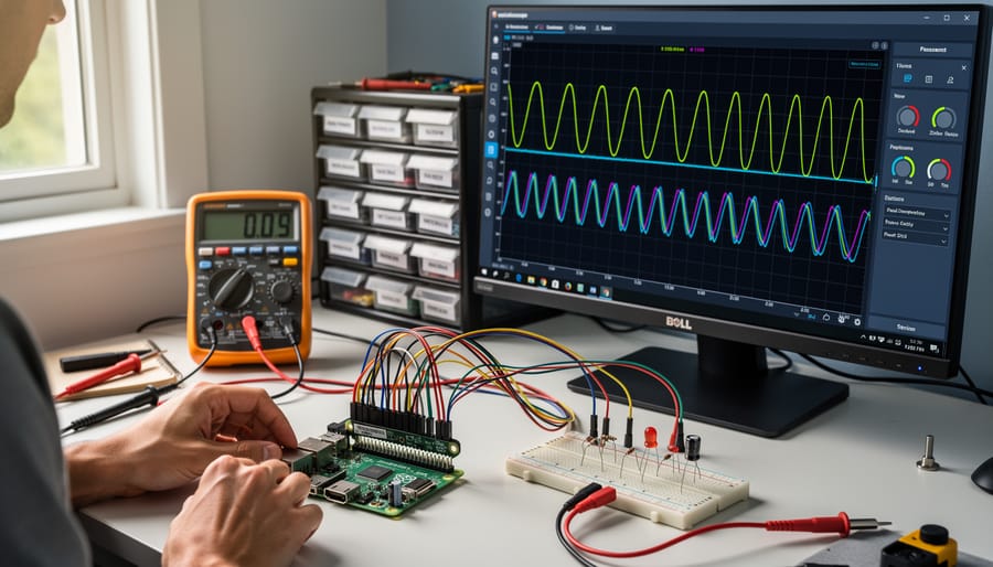
Transform your Raspberry Pi into a professional-grade oscilloscope capable of measuring signals up to 20MHz by installing PicoScope software and connecting a low-cost ADC module—you’ll match 80% of commercial instrument functionality at one-tenth the cost. Build a logic analyzer using GPIO pins and sigrok software to debug I2C, SPI, and UART protocols in real-time, enabling troubleshooting that previously required $500+ equipment. Create a programmable function generator that outputs sine, square, and triangle waves from DC to 100kHz using a simple DAC chip and Python script, perfect for testing amplifier circuits and audio equipment.
DIY electronic test equipment represents a practical intersection of learning and utility. When building Raspberry Pi projects, you gain both measurement capabilities for future projects and hands-on understanding of how professional instruments actually work. The Raspberry Pi’s processing power, GPIO flexibility, and active software ecosystem make it an ideal platform for creating oscilloscopes, spectrum analyzers, multimeters, and signal generators that handle most hobbyist and educational needs.
Commercial test equipment costs hundreds or thousands of dollars, putting proper instrumentation out of reach for students, hobbyists, and makerspaces with limited budgets. A Raspberry Pi-based approach reduces entry costs to $50-150 while teaching fundamental electronics principles. You’ll understand sampling theory, signal processing, and measurement techniques more deeply by building the tools yourself rather than using them as black boxes. This guide shows you exactly what’s achievable, what components you need, and where DIY solutions excel or fall short compared to commercial alternatives.
Why Raspberry Pi Makes Perfect DIY Test Equipment

Processing Power Meets Affordability
The Raspberry Pi delivers impressive computational muscle that punches well above its modest price tag. Even the entry-level Raspberry Pi 4 offers a quad-core processor capable of handling complex signal processing tasks, running at speeds sufficient for real-time data acquisition and analysis. When you consider that professional oscilloscopes can cost thousands of dollars, building equivalent functionality with a Raspberry Pi for under $100 becomes remarkably attractive.
The platform excels at tasks like digital signal processing, waveform analysis, and automated data logging. With its built-in GPIO pins and support for analog-to-digital converters, you can capture signals at sampling rates suitable for audio analysis, sensor monitoring, and basic RF measurements. The Raspberry Pi’s ability to run Python and other programming languages means you can implement sophisticated algorithms for FFT analysis, filtering, and measurement automation.
What makes this particularly valuable is the software ecosystem. Open-source tools like GNU Radio and libraries such as NumPy and SciPy provide professional-grade signal processing capabilities without licensing fees. You’re essentially getting research-lab functionality at hobbyist prices, with the added benefit of complete customization to fit your specific testing needs.
GPIO Pins: Your Gateway to the Analog World
The Raspberry Pi’s GPIO (General Purpose Input/Output) pins are your bridge between the digital and physical worlds. These versatile pins can read analog signals from sensors and control external circuits, making them essential for DIY test equipment. While GPIO pins natively handle digital signals, you’ll need analog-to-digital converters (ADCs) to measure voltages, temperatures, and other analog values.
This is where add-on boards become game-changers. HATs (Hardware Attached on Top) and expansion boards transform your Pi into a capable measurement platform. Popular options include ADC boards like the MCP3008, which adds eight analog input channels, and specialized boards for oscilloscopes or data acquisition. These additions unlock capabilities like multi-channel voltage monitoring, signal generation, and real-time data logging.
Getting started with GPIO interfacing projects is straightforward. The Pi’s software libraries, particularly Python’s GPIO libraries, make programming intuitive even for beginners. You’ll connect sensors through simple circuits, configure pin modes in code, and start collecting measurements within minutes. Whether you’re building a basic multimeter or a sophisticated data logger, GPIO pins provide the foundation for expanding your Raspberry Pi into professional-grade test equipment.
Essential DIY Test Instruments You Can Build
Digital Oscilloscope
Building a DIY oscilloscope with your Raspberry Pi opens up a world of signal analysis possibilities. By connecting an ADC (Analog-to-Digital Converter) module like the MCP3008 or ADS1115 to your Pi’s GPIO pins, you can create a functional scope for low-frequency applications. These budget-friendly ADCs typically offer sample rates between 200 kHz and 1 MHz, making them suitable for audio circuits, sensor testing, and slow digital signals.
For improved performance, consider USB-based oscilloscope modules that connect directly to your Pi. These devices can achieve bandwidths up to 20 MHz and sample rates of 50-100 MS/s, bringing you closer to entry-level commercial scope capabilities. Software like OpenHantek or SignalScope transforms your Pi into a visual analysis station, while PicoScope’s Linux compatibility offers professional-grade features for serious hobbyists.
Your DIY oscilloscope excels at debugging Arduino projects, analyzing audio amplifiers, checking PWM signals, and troubleshooting sensor outputs. While it won’t replace a professional oscilloscope for high-frequency work or critical measurements, it provides tremendous value for learning electronics fundamentals and handling most hobbyist needs. The ability to capture, store, and analyze waveforms digitally adds functionality that traditional analog scopes can’t match at this price point.
Logic Analyzer
A DIY logic analyzer lets you capture and visualize digital signals across multiple channels simultaneously, making it invaluable for debugging communication protocols like I2C, SPI, and UART. You can build a capable 8-channel analyzer using a Raspberry Pi Pico and the open-source sigrok PLA firmware, which costs under $10 compared to commercial options starting at $100.
The setup is straightforward: flash the Pico with sigrok firmware, connect your test signals to GPIO pins, and interface with your computer via USB. On the software side, PulseView provides an intuitive interface for capturing and analyzing signals. It includes protocol decoders for dozens of common standards, automatically translating raw signal data into human-readable formats. The sigrok ecosystem supports Windows, Linux, and macOS, ensuring broad compatibility.
While commercial logic analyzers offer higher sample rates (often 100MHz+) and more channels, a Pico-based analyzer handles typical hobbyist projects with 20-50MHz sampling and 8 channels. For most Arduino or ESP32 debugging tasks, this performance proves more than adequate. You’ll benefit from professional-grade protocol decoding capabilities without the hefty price tag, though critical timing analysis in high-speed applications may require commercial equipment. The open-source nature also means continuous community improvements and expanding protocol support.
Function Generator and Signal Source
Building a function generator with your Raspberry Pi opens up exciting possibilities for circuit testing and signal generation. Using affordable DAC (Digital-to-Analog Converter) modules like the MCP4725 or PCM5102, you can create arbitrary waveform generators that produce sine, square, triangle, and custom waves. These DIY generators typically achieve frequency ranges from a few hertz up to several hundred kilohertz, perfect for testing amplifiers, filters, and oscillators.
Python libraries like RPi.GPIO and smbus make programming your waveforms straightforward. You can generate precise frequencies for calibrating circuits or create complex modulated signals for advanced testing. The flexibility of software-defined waveforms means you can easily adjust amplitude, frequency, and shape without hardware changes.
These generators prove invaluable for audio projects, speaker testing, and educational demonstrations. While they may not match the upper frequency limits of commercial units, they excel at low-frequency applications and offer unmatched customization through code.
Network Analyzer
Building an RF network analyzer with a Raspberry Pi opens up antenna testing and impedance measurement capabilities at a fraction of commercial costs. The most accessible approach uses an AD9850 or AD9851 DDS signal generator paired with an AD8302 gain/phase detector IC to measure reflection coefficients and transmission characteristics. Your Raspberry Pi controls the frequency sweep and processes the returned data to display Smith charts and S-parameters.
Practical frequency coverage typically ranges from 1 MHz to 60 MHz with basic setups, though adding directional couplers and bridge circuits extends usefulness for HF antenna work. For higher frequencies, consider pairing your Pi with NanoVNA hardware as an external measurement head, using the Pi for enhanced data logging and analysis.
Essential add-ons include SMA connectors, calibration loads (50-ohm, open, and short), and quality coaxial cables. While DIY network analyzers won’t match lab-grade accuracy, they’re excellent for tuning homebrew antennas, measuring cable losses, and learning RF fundamentals hands-on.
Multimeter and Data Logger
Building a multimeter with data logging transforms your Raspberry Pi into a precision measurement tool that goes beyond commercial options. Using ADC modules like the ADS1115 (16-bit resolution) and current sensing ICs such as the INA219, you can measure voltage, current, and resistance with impressive accuracy. The real advantage comes from programmable data logging—perfect for monitoring battery discharge curves, solar panel performance, or long-term circuit behavior over hours or days.
Your Pi can store measurements to CSV files or databases, making analysis straightforward with Python libraries like matplotlib or pandas. For real-time monitoring, implement web-based dashboards using Flask or explore graphical display options with touchscreens showing live plots and statistics. This setup excels at unattended monitoring tasks that would drain handheld meter batteries. Add email or push notifications when measurements exceed thresholds, creating an intelligent monitoring system that alerts you to potential issues automatically.
Hardware Components and Add-On Boards You’ll Need
ADC and DAC Modules
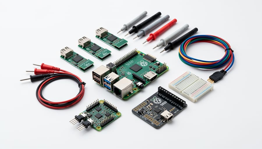
Selecting the right ADC and DAC modules is crucial for building accurate test equipment. For oscilloscopes and data loggers, the MCP3008 offers an accessible entry point with 10-bit resolution and eight channels at 200 kSPS, perfect for audio-frequency measurements. If you need higher precision, the ADS1115 provides 16-bit resolution across four channels, though at a slower 860 SPS rate, making it ideal for voltage measurements and sensor readings.
For function generators requiring analog output, the MCP4725 stands out as a reliable 12-bit DAC with I2C interface, capable of generating clean waveforms up to several kilohertz. More demanding applications might warrant the AD5693, offering 16-bit resolution for precise signal generation.
Sample rate considerations matter significantly. Low-speed applications like temperature monitoring work fine with the ADS1115, while audio-range oscilloscopes need faster converters like the MCP3008 or even the ADS1015 at 3.3 kSPS. Remember that higher resolution doesn’t always mean better performance—a 16-bit converter sampling at 10 Hz won’t capture fast transients that a 10-bit converter at 200 kSPS would catch easily.
Most modules connect via SPI or I2C protocols, with extensive Python libraries available, making integration straightforward even for beginners. Consider starting with lower-resolution modules to understand the fundamentals before investing in premium converters.
Signal Conditioning Circuits
Before connecting your Raspberry Pi to real-world signals, you need signal conditioning circuits to protect your hardware and ensure accurate measurements. The Pi’s GPIO pins operate at 3.3V and can be easily damaged by higher voltages or incorrect current levels.
Voltage dividers are essential for scaling down signals to safe levels. For example, measuring a 12V circuit requires a resistor network that reduces the voltage to under 3.3V before reaching your Pi. A simple two-resistor divider using 10kΩ and 3.3kΩ resistors works well for this purpose.
Protection circuits prevent damage from voltage spikes and reverse polarity. Adding a series resistor (typically 1kΩ) and a 3.3V Zener diode provides basic overvoltage protection. For AC signals or battery monitoring, include a reverse-biased diode to block negative voltages.
Amplifiers boost weak signals like those from sensors or small AC ripples. Operational amplifiers like the LM358 are affordable and easy to implement on a breadboard. They’re particularly useful for building oscilloscopes or sensitive voltage measurement tools.
Always test your conditioning circuits with a multimeter before connecting them to your Raspberry Pi. This simple precaution prevents costly mistakes and ensures your DIY test equipment delivers reliable, safe measurements.
Essential Accessories
Building professional-looking test equipment requires more than just the Raspberry Pi. Quality probes are essential—invest in BNC or banana plug connectors for reliable signal connections. For oscilloscopes and logic analyzers, shielded probes minimize noise interference. A clear display matters too; 7-inch touchscreens work great for portable designs, while HDMI monitors suit benchtop setups.
Choose enclosures that provide proper ventilation and easy access to ports. 3D-printed cases offer customization, while off-the-shelf project boxes speed up assembly. Don’t overlook power supplies—ensure stable 5V delivery with at least 3A capacity for demanding projects. USB-C power delivery adapters work well for modern Raspberry Pi models.
Additional components like jumper wires, terminal blocks, and voltage dividers help interface with circuits safely. Quality connectors and proper shielding transform hobby projects into reliable instruments you’ll actually want to use daily.
Software and Programming Tools
Python Libraries for Measurement
Python makes it incredibly easy to transform your Raspberry Pi into powerful test equipment by providing libraries that handle the heavy lifting. For direct hardware interfacing, RPi.GPIO lets you control the Pi’s GPIO pins to read digital signals and trigger measurements, while spidev and smbus enable communication with external ADCs, sensors, and integrated circuits through SPI and I2C protocols respectively. These libraries form the foundation for capturing real-world electronic data.
Once you’ve collected measurements, Python’s data analysis tools come into play. NumPy excels at processing large arrays of measurement data, performing calculations like averaging, filtering, and statistical analysis with just a few lines of code. For visualization, matplotlib transforms your raw numbers into professional-looking graphs, oscilloscope traces, and frequency plots that make interpreting results straightforward. Together, these libraries create a complete measurement ecosystem that rivals commercial equipment in many applications.
The beauty of this approach is accessibility. All these libraries are free, well-documented, and supported by active communities. Whether you’re building a simple voltmeter or a complex spectrum analyzer, you’ll find plenty of code examples and tutorials to get started quickly.
Open-Source Test Software
Building DIY test equipment becomes infinitely more practical when paired with powerful open-source software that transforms your Raspberry Pi into a professional-grade measurement interface. Let’s explore the standout applications that make this possible.
Sigrok leads the pack as a comprehensive signal analysis suite supporting dozens of hardware devices. This versatile platform handles logic analyzers, oscilloscopes, multimeters, and more through a unified interface. The PulseView frontend offers intuitive protocol decoding for I2C, SPI, UART, and countless other standards, making troubleshooting digital circuits straightforward even for beginners.
OpenHantek provides dedicated oscilloscope functionality, offering impressive features like FFT analysis, measurement cursors, and trigger controls. While originally designed for Hantek USB scopes, it adapts well to various ADC hardware configurations with your Raspberry Pi.
For specialized tasks, consider rtl-sdr software for spectrum analysis using inexpensive USB dongles, or GNU Radio for software-defined radio applications. The Python-based matplotlib and scipy libraries enable custom measurement applications tailored to your specific needs.
These applications shine brightest when combined with affordable hardware adapters. Most run smoothly on Raspberry Pi 3 or newer models, though compute-intensive operations like high-speed sampling benefit from Pi 4’s enhanced processing power. The beauty of open-source tools lies in their flexibility—you can customize interfaces, add features, and integrate multiple instruments into unified measurement solutions without licensing restrictions.
Creating Custom Interfaces
Making your test equipment truly user-friendly means creating interfaces that are intuitive and accessible. Python’s Tkinter library offers a straightforward way to build graphical interfaces on your Raspberry Pi, allowing you to display waveforms, adjust settings with sliders, and save measurements with simple button clicks. For those wanting remote access, web-based interfaces using Flask or Node-RED let you control your equipment from any device on your network—perfect for monitoring experiments from across the room or documenting results on your phone. These tools require minimal coding experience, with plenty of tutorials available online to get you started quickly.
Step-by-Step: Building Your First Oscilloscope
What You’ll Need
To build your DIY oscilloscope, you’ll need a Raspberry Pi 4 (4GB or 8GB model, around $55-75), an ADS1115 16-bit ADC module ($8-12), and a simple voltage divider circuit using resistors. Additional components include jumper wires ($5), a breadboard ($5), and a 5-inch touchscreen display ($35-45) for portable operation, though you can use any HDMI monitor initially.
For the complete setup, budget approximately $120-150 total. You’ll also need a microSD card with Raspberry Pi OS installed, a power supply, and basic soldering equipment if you want a permanent circuit board setup. Optional accessories include a 3D-printed enclosure (filament costs around $5-10) and BNC connectors ($10-15) for professional probe connections.
The software component is free, using Python libraries like matplotlib and RPi.GPIO. All electronic components are widely available from suppliers like Adafruit, SparkFun, or Amazon, making this project accessible for most hobbyists.
Hardware Assembly
Let’s start building your DIY oscilloscope by assembling the hardware components. This process is straightforward and perfect for beginners.
First, connect your ADS1115 ADC module to the Raspberry Pi’s GPIO pins. Wire the VDD pin to 3.3V, GND to ground, SDA to GPIO 2, and SCL to GPIO 3. These I2C connections allow the Pi to communicate with the ADC and read voltage measurements.
Next, prepare your signal input circuit. Connect a BNC connector or probe jack to the A0 input of the ADS1115. This will serve as your primary measurement channel. To protect your expensive Raspberry Pi from voltage spikes, add a simple protection circuit using a voltage divider with two resistors (10kΩ and 1kΩ) to scale down incoming signals. Include a 3.3V Zener diode between the ADC input and ground as an additional safety measure.
For multiple channels, wire additional inputs to A1, A2, and A3 following the same pattern. Double-check all connections before powering up, ensuring no shorts between power rails. Once verified, power on your Raspberry Pi and confirm the ADC module appears when running the i2cdetect command. This confirms successful hardware communication and readiness for software configuration.
Software Installation and Configuration
Getting your DIY test equipment up and running starts with preparing your Raspberry Pi. Begin by downloading the latest Raspberry Pi OS from the official website and flashing it to your microSD card using tools like Raspberry Pi Imager or Balena Etcher. Once booted, update your system with the commands sudo apt update and sudo apt upgrade to ensure compatibility.
Next, install Python libraries essential for interfacing with sensors and ADCs. Use pip to install packages like Adafruit-Blinka, spidev, and RPi.GPIO. For graphical interfaces, install libraries such as matplotlib or PyQt5 depending on your display preferences.
You can either write custom control code or download existing projects from repositories like GitHub. Many developers share complete oscilloscope and multimeter projects with well-documented code. Look for projects matching your specific ADC chip and sensor configuration to minimize troubleshooting.
Calibration is crucial for accurate measurements. Compare your readings against known voltage references or a commercial multimeter. Adjust scaling factors in your code to compensate for component tolerances and voltage divider ratios. Document your calibration values for future reference.
Test basic functionality with simple voltage measurements before tackling complex signals. This methodical approach helps identify issues early and builds confidence in your equipment’s reliability.
Testing and Troubleshooting
Test your oscilloscope by connecting a known signal source like the Raspberry Pi’s PWM output. Run the visualization software and verify waveforms appear correctly. Common issues include noise interference, which you can reduce by adding shielding or shorter probe cables. If readings seem unstable, check your ground connections and ensure adequate power supply to your ADC. Calibrate using a signal generator if available, or compare readings against a commercial scope. For better performance, keep probe leads twisted together to minimize electromagnetic interference, add ferrite beads to USB cables, and enable hardware SPI for faster sampling rates. Remember that DIY equipment has limitations compared to professional tools, but it’s perfect for learning and basic troubleshooting tasks.
Accuracy, Limitations, and When to Use Commercial Equipment
Understanding Measurement Accuracy
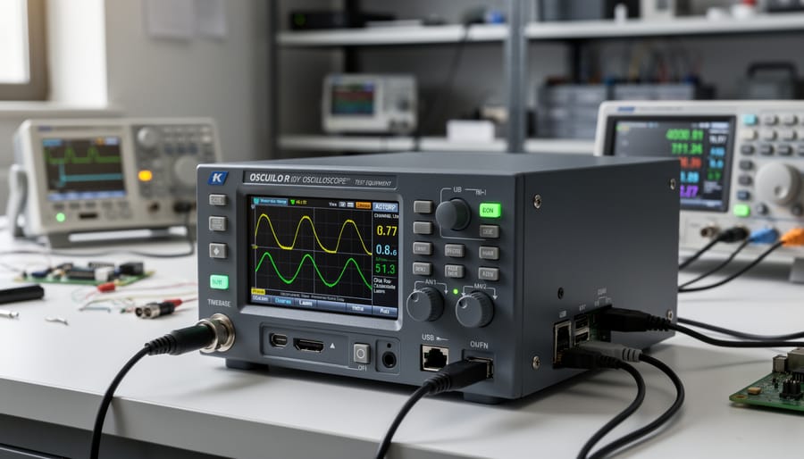
Let’s be honest about what you can expect from DIY test equipment. While your Raspberry Pi-based instruments won’t match the precision of professional lab gear costing thousands of dollars, they’re surprisingly capable for most hobbyist needs. A well-calibrated DIY oscilloscope can achieve 8-10 bit resolution with accuracy within 2-5%, which is perfectly adequate for audio projects, Arduino debugging, and basic electronics work.
Several factors affect your measurement accuracy. Temperature fluctuations impact component values, your power supply quality matters more than you might think, and proper shielding reduces electrical noise. The analog-to-digital converters you choose become the bottleneck, so investing in quality ADC modules pays dividends.
Commercial lab equipment offers superior noise rejection, wider bandwidth, and factory calibration, but costs 10-100 times more. Your DIY multimeter might show 0.5% accuracy versus 0.01% for professional models. For learning electronics, troubleshooting circuits, and educational purposes, this difference rarely matters. Think of it this way: if you need to measure 5 volts, being off by 0.025V versus 0.0005V won’t affect most hobbyist projects. Focus on understanding your equipment’s limitations and building within those boundaries.
When DIY Equipment Falls Short
While DIY test equipment opens exciting possibilities for hobbyists and educators, certain situations demand professional-grade instruments. High-frequency work beyond 100 MHz typically requires calibrated oscilloscopes and spectrum analyzers, as DIY solutions struggle with signal integrity and accuracy at these speeds. Safety-critical applications, particularly those involving mains voltage or medical devices, need certified equipment with proper isolation and protection features that homemade tools cannot guarantee. If you’re working on products requiring FCC certification, EMC testing, or regulatory compliance, professional equipment with traceable calibration certificates becomes mandatory. Similarly, precision measurements for commercial products or research applications need the repeatability and accuracy that only calibrated lab equipment provides. Understanding these boundaries helps you choose the right tool for each project while staying safe and compliant with industry standards.
Taking Your Projects Further
Improving Your Instruments
Once you’ve built your basic DIY test equipment, there’s plenty of room for improvement. Consider upgrading to higher-resolution ADCs for more precise measurements—a 16-bit or 24-bit converter can dramatically improve accuracy over the Raspberry Pi’s basic inputs. Adding features like data logging to SD cards, wireless connectivity for remote monitoring, or touchscreen displays can transform a simple project into a professional-grade tool.
Don’t overlook the physical aspects either. A sturdy 3D-printed or laser-cut enclosure not only protects your circuitry but also makes your instrument look more polished and easier to handle. Adding proper labeling, LED indicators, and accessible controls improves the user experience significantly.
For software upgrades, explore creating custom graphical interfaces using Python libraries like Tkinter or web-based dashboards. These make interpreting data faster and more intuitive. Remember, each improvement teaches you something new about electronics and programming while making your instrument more capable and enjoyable to use.
Community Resources and Projects
The DIY test equipment community offers fantastic resources to expand your knowledge and discover new project ideas. Start with the EEVblog Forum, where experienced engineers and hobbyists discuss test equipment builds and troubleshooting. For open-source designs and code, explore GitHub repositories like “PyLab” and “Raspberry Pi Oscilloscope” that provide complete schematics and software you can adapt for your projects.
YouTube channels such as GreatScott!, ElectroBOOM, and Andreas Spiess feature detailed build tutorials and performance comparisons of DIY instruments. Reddit communities like r/raspberry_pi and r/AskElectronics are excellent for getting quick answers and sharing your own builds. The official Raspberry Pi Forums also host dedicated threads on measurement projects. Don’t overlook Hackaday.io and Instructables, where makers publish comprehensive project guides with step-by-step instructions. These platforms connect you with a supportive community ready to help troubleshoot issues and inspire your next build. Bookmark these resources and engage actively to accelerate your learning journey.
Building your own electronic test equipment isn’t just about saving money, though the cost benefits are significant. It’s about understanding the tools you use, gaining confidence in electronics design, and developing troubleshooting skills that will serve you throughout your maker journey. Every component you solder, every calibration you perform, and every measurement you take deepens your knowledge in ways that simply buying commercial equipment never could.
Start small. A simple multimeter project or basic oscilloscope gives you immediate utility while teaching fundamental concepts. As you complete your first build, you’ll discover that the process itself is rewarding, and you’ll naturally want to tackle more complex instruments. The Raspberry Pi ecosystem makes this progression smoother than ever, with extensive community support and resources available for troubleshooting.
Don’t let perfectionism hold you back. Your first DIY test equipment doesn’t need to match laboratory-grade precision to be valuable. Even a basic tool you’ve built yourself provides learning opportunities and practical measurements for hobbyist projects. If you’re new to hardware projects, consider exploring Raspberry Pi starter projects to build foundational skills.
Ready to begin? Pick one project that excites you, gather your components, and start building today.