
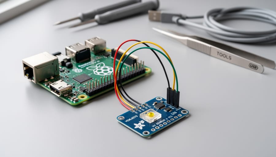
Connecting an Adafruit UV sensor to your Raspberry Pi takes about 30 minutes and requires only basic soldering skills and familiarity with I2C communication. The most popular option, the VEML6070 or SI1145 UV sensor breakout from Adafruit, provides accurate ultraviolet light measurements that you can read through Python code, making it perfect for weather stations, sun exposure monitors, and outdoor robotics projects.
UV sensors measure the intensity of ultraviolet radiation, typically outputting data in UV index format or raw sensor values that you can convert. While invisible to the human eye, UV radiation plays a crucial role in everything from vitamin D production to skin damage, making accurate measurement valuable for health-conscious projects and environmental monitoring.
The setup process involves wiring the sensor to your Raspberry Pi’s GPIO pins, enabling I2C communication in the Raspberry Pi configuration, and installing Adafruit’s CircuitPython libraries to handle data collection. You’ll get real-time UV readings that update every few seconds, with values you can log, display on a screen, or trigger actions based on threshold levels.
This guide walks you through the complete integration process, from identifying which pins to connect to writing your first UV monitoring script. Whether you’re building a smart garden system that alerts you to harmful UV levels or a portable sun safety device, you’ll have a working UV sensor feeding data to your Raspberry Pi by the end of this tutorial.
Understanding the Adafruit UV Sensor
Adafruit offers two primary UV sensor breakout boards for makers: the VEML6070 and the Si1145. The VEML6070 focuses exclusively on UV-A light detection and provides straightforward UV index readings through a simple I2C interface. It’s compact, affordable, and ideal when you only need UV monitoring. The Si1145, by contrast, is a multi-function sensor that measures UV index alongside visible light and infrared, making it suitable for projects requiring comprehensive light analysis in a single component.
Both sensors output UV index values, a standardized measurement that ranges from 0 to 11+ and indicates the strength of ultraviolet radiation. A reading of 0-2 is considered low exposure, 3-5 is moderate, 6-7 is high, 8-10 is very high, and 11+ is extreme. These numbers directly correlate to sun safety recommendations, which makes them valuable for real-world health applications.
The practical applications extend beyond simple UV monitoring. Weather enthusiasts build personal weather stations that log UV exposure alongside temperature and humidity. Home automation projects use UV readings to control motorized awnings or send smartphone alerts when UV levels become dangerous for outdoor activities. Health-conscious makers create wearable devices that track cumulative UV exposure during outdoor work or recreation.
These sensors communicate through I2C, a two-wire protocol that lets your Raspberry Pi talk to multiple sensors using just two GPIO pins. Think of I2C as a party line where the Raspberry Pi acts as the manager, asking each sensor for data by calling its unique address. The sensor responds with its measurements, all traveling along the same two wires (SCL for timing and SDA for data). This efficiency means you can connect the UV sensor alongside other I2C devices without consuming extra GPIO pins.
What You’ll Need for This Project
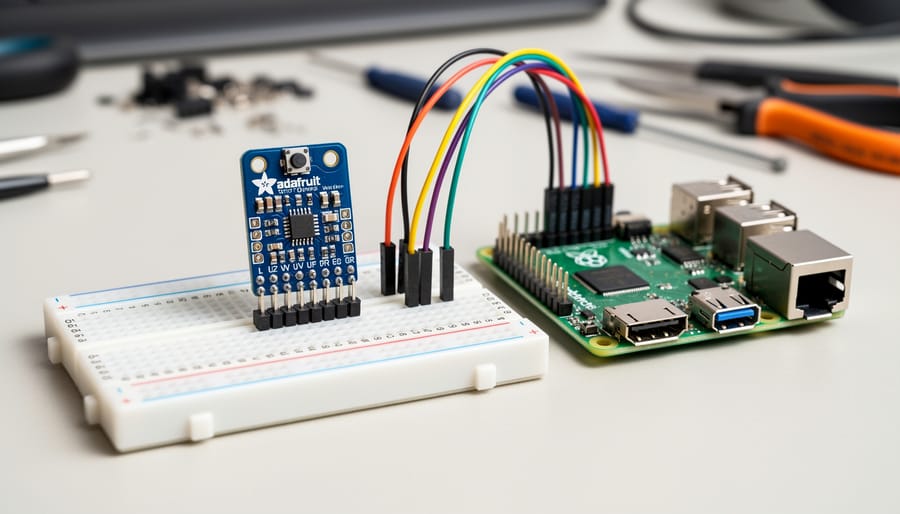
Before you connect your UV sensor, gather the following components and software to ensure a smooth integration process. Having everything ready prevents mid-project interruptions and helps you verify compatibility upfront.
Required Hardware Components:
- Adafruit VEML6070 UV Index Sensor breakout board (approximately $5-8) or Adafruit Si1145 Digital UV Index sensor (approximately $10-12)
- Raspberry Pi 3 Model B, Pi 4, or Pi Zero W with GPIO header pins
- Female-to-female jumper wires (minimum 4 wires, preferably a set of 40)
- Half-size breadboard (optional but recommended for beginners)
- MicroSD card with at least 8GB capacity
- 5V 2.5A power supply for Raspberry Pi
The VEML6070 offers excellent value for basic UV monitoring, while the Si1145 provides additional infrared and visible light sensing capabilities. Both sensors communicate via I2C protocol and work identically with Raspberry Pi GPIO pins.
Software Requirements:
- Raspberry Pi OS (Bullseye or newer, 32-bit or 64-bit)
- Python 3.7 or higher (pre-installed on recent Raspberry Pi OS versions)
- Internet connection for downloading libraries during setup
Optional Tools That Make Integration Easier:
- Anti-static wrist strap for handling sensitive electronics
- Small screwdriver set for securing components if building a permanent enclosure
- Multimeter for verifying power supply voltage and troubleshooting connections
- Protective case or enclosure for outdoor deployment
Budget around $20-30 total if you already own a Raspberry Pi, or $60-80 for a complete starter setup. Most components except the sensor itself are reusable across multiple projects.
Safety and Pre-Integration Checklist

Before connecting your UV sensor, take these precautions to protect both your components and ensure reliable operation.
Handle the Adafruit UV sensor by its edges and store it in anti-static packaging when not in use. Work on a non-conductive surface like wood or an ESD mat, and consider using an anti-static wrist strap if you’re working in a low-humidity environment where static builds up easily.
Verify your Raspberry Pi’s power supply meets the minimum requirements. The UV sensor draws minimal current, but your Pi needs a stable 5V power source with at least 2.5A capacity to prevent voltage drops during operation. Using an underpowered supply causes erratic sensor readings and potential GPIO damage.
Check for I2C address conflicts if you’re already using other I2C sensors with your Raspberry Pi. The VEML6070 UV sensor typically uses addresses 0x38 and 0x39, while the Si1145 uses 0x60. Run `i2cdetect -y 1` before adding the UV sensor to see which addresses are occupied. If you find a conflict, you’ll need to adjust your sensor arrangement or use an I2C multiplexer.
Inspect your Raspberry Pi’s GPIO pins before starting. Look for bent pins, corrosion, or previous solder damage. Gently straighten any bent pins with needle-nose pliers, but if you see physical damage to the pin headers or board traces, do not proceed until you’ve replaced the damaged components or used alternative GPIO pins.
Step 1: Prepare Your Raspberry Pi Environment
Before connecting your Adafruit UV sensor, you need to configure your Raspberry Pi’s operating system and install the required software libraries. This preparation takes about ten minutes and ensures smooth communication with the sensor.
Enable the I2C Interface
The Adafruit UV sensor communicates through the I2C protocol, which is disabled by default on Raspberry Pi. Open a terminal and type:
“`
sudo raspi-config
“`
Navigate to “Interface Options”, then select “I2C” and choose “Yes” to enable it. Exit raspi-config and reboot your Raspberry Pi when prompted, or manually reboot with `sudo reboot`.
Update Your System
After rebooting, update your package lists and installed software to avoid compatibility issues:
“`
sudo apt update
sudo apt upgrade -y
“`
This process might take several minutes depending on how recently you’ve updated. The `-y` flag automatically confirms installation prompts.
Install Required Python Libraries
You’ll need specific Python libraries to communicate with the UV sensor. Start by installing the I2C tools and Python development packages:
“`
sudo apt install -y python3-pip python3-dev i2c-tools
“`
The `i2c-tools` package includes the `i2cdetect` command you’ll use later to verify sensor connection.
Next, install the Adafruit CircuitPython libraries. These provide pre-written functions for reading UV data:
“`
pip3 install adafruit-circuitpython-veml6070
“`
Or, if you’re using the Si1145 sensor model:
“`
pip3 install adafruit-circuitpython-si1145
“`
Install both if you’re unsure which sensor model you have. You can also install the Adafruit Blinka library for broader compatibility:
“`
pip3 install adafruit-blinka
“`
Your Raspberry Pi is now configured and ready for the physical sensor connection. The I2C interface is active, your system is updated, and all necessary software libraries are installed.
Step 2: Wire the UV Sensor to Raspberry Pi
With your Raspberry Pi environment prepared, you’re ready to make the physical connections between the Adafruit UV sensor and your Raspberry Pi. Proper wiring is critical for both sensor functionality and preventing damage to your components.
The Adafruit UV sensor uses four essential connections. The VIN (power input) pin supplies power to the sensor. Connect this to a 3.3V pin on your Raspberry Pi, specifically, physical pin 1 or pin 17 on the GPIO header. While some Adafruit sensors tolerate 5V, the VEML6070 and Si1145 operate at 3.3V logic levels, making this the safest choice.
The GND (ground) pin completes the power circuit. Connect it to any ground pin on the Raspberry Pi, such as physical pin 6, 9, 14, 20, 25, 30, 34, or 39. Ground provides a common reference voltage for all components and ensures stable operation.
For data communication, you’ll use two I2C pins. The SCL (Serial Clock) pin carries the clock signal that synchronizes data transfer between devices. Connect the sensor’s SCL pin to GPIO 3 (physical pin 5) on the Raspberry Pi, this is the standard I2C clock line. The SDA (Serial Data) pin transmits the actual data. Connect the sensor’s SDA pin to GPIO 2 (physical pin 3), the Raspberry Pi’s designated I2C data line.
These specific GPIO pins are crucial because the Raspberry Pi’s hardware I2C interface only functions on GPIO 2 and GPIO 3. Using other pins would require software-based I2C emulation, which introduces timing issues and reduces reliability.
Double-check each connection before applying power. A misplaced wire connecting VIN to 5V could damage the sensor, while reversed SCL and SDA connections will prevent communication entirely.
Step 3: Verify Sensor Detection and I2C Communication
With your sensor wired and I2C enabled, it’s time to confirm your Raspberry Pi can actually see the UV sensor. Open a terminal and run this command:
“`
sudo i2cdetect -y 1
“`
You’ll see a grid of numbers and dashes. The VEML6070 sensor appears at two addresses, 0x38 and 0x39, because it uses both for reading different data registers. The Si1145 sensor shows up at address 0x60. If you see these hexadecimal numbers instead of dashes at those positions, congratulations, your Raspberry Pi has established I2C communication with the sensor.
The I2C address is essentially your sensor’s unique identifier on the communication bus. Think of it like a street address that tells your Raspberry Pi where to send requests for UV data. Multiple I2C devices can share the same two wires because each responds only to its specific address.
If you see only dashes where your sensor’s address should appear, something’s wrong. First, double-check your wiring, especially the SDA and SCL connections, which are the actual communication lines. A loose jumper wire is the most common culprit. Next, verify the sensor is receiving power by confirming your 3.3V and ground connections are solid.
Still no detection? Try running `sudo i2cdetect -y 0` instead. Older Raspberry Pi models use I2C bus 0 rather than bus 1. You can also run `ls /dev/i2c*` to see which I2C buses your Pi recognizes.
If the sensor appears but shows “UU” instead of its address, another program is already using it, which actually confirms it’s working. Stop any Python scripts you might have running and try the detection command again.
Step 4: Write Python Code to Read UV Data
After confirming your sensor is communicating properly with the Raspberry Pi, you’re ready to write Python code that actually reads UV data. This script forms the foundation for any UV monitoring project you build.
Start by creating a new Python file in your project directory. Open your terminal and type `nano uv_sensor.py` to create and edit the file.
First, import the necessary libraries at the top of your script:
“`python
import time
import board
import adafruit_veml6070
“`
The `board` library provides access to your Raspberry Pi’s I2C pins, while `adafruit_veml6070` contains the sensor-specific code. If you’re using the Si1145 sensor instead, replace the third line with `import adafruit_si1145`.
Next, initialize the I2C connection and create the sensor object:
“`python
i2c = board.I2C()
uv_sensor = adafruit_veml6070.VEML6070(i2c)
“`
This establishes communication between your Pi and the sensor using the I2C protocol you verified in the previous step.
Now add the main reading loop:
“`python
while True:
uv_raw = uv_sensor.uv_raw
risk_level = uv_sensor.get_index(uv_raw)
print(f”UV Reading: {uv_raw}”)
print(f”Risk Level: {risk_level}”)
time.sleep(2)
“`
The `uv_raw` variable contains the sensor’s direct reading, which is a numerical value representing UV intensity. The `get_index` method converts this raw reading into a standardized UV index value between 0 and 11+.
Understanding the UV index scale helps you interpret results: 0-2 indicates low risk, 3-5 is moderate, 6-7 is high, 8-10 is very high, and 11+ represents extreme UV exposure. Your sensor will return these classifications automatically.
The `time.sleep(2)` command pauses for two seconds between readings, preventing data overload. You can adjust this interval based on your project needs, slower intervals conserve processing power while faster updates provide near-real-time monitoring.
Save the file with Ctrl+X, then Y, then Enter. Run your script with `python3 uv_sensor.py` and you’ll see UV readings appear every two seconds. Test the sensor by moving it between indoor and outdoor locations to verify changing values.
Testing and Verifying Your UV Sensor Integration
After writing your Python code, proper testing confirms your UV sensor functions reliably. Start verification indoors, then move to controlled outdoor conditions to validate against real UV exposure.
Indoor Baseline Test
Run your Python script in a room away from direct sunlight. Indoor UV index readings should register 0-1, confirming the sensor responds to minimal UV exposure. Values above 2 indoors suggest calibration issues or interference from artificial UV sources like germicidal lamps.
Outdoor Validation
Take your setup outdoors during midday (10 AM to 2 PM) for peak UV conditions. Expected readings range from 3-7 on partly cloudy days to 8-11+ in direct summer sun. Compare your sensor output with local weather service UV forecasts, readings within ±1-2 index points indicate proper calibration.
Complete Verification Process
- Run your Python script continuously for 10 minutes indoors and record readings every 30 seconds to confirm stable output without random spikes.
- Move the setup outdoors into shade, then direct sunlight, watching values increase appropriately, shade readings should be 30-50% lower than full sun.
- Verify I2C communication remains stable by checking for consistent readings without “sensor not found” errors during extended operation.
- Log data for 2-3 hours spanning changing light conditions to confirm the sensor tracks UV intensity fluctuations correctly.
Successful integration means consistent readings that align with expected UV conditions, stable I2C communication without dropouts, and logical value changes as light conditions shift. For projects requiring remote monitoring, consider adding wireless RF capability to transmit UV data from outdoor sensors to an indoor Raspberry Pi base station.
If readings seem erratic or frozen, verify your wiring connections and confirm the sensor faces upward with its sensing window unobstructed.
Troubleshooting Common Integration Issues
When your UV sensor integration doesn’t work as expected, systematic troubleshooting will identify the issue quickly. Here’s how to diagnose and fix the most common problems.
Sensor Not Detected on I2C Bus
If `i2cdetect -y 1` shows no device at address 0x38 or 0x10, check your wiring first. Verify that SDA connects to GPIO 2 and SCL connects to GPIO 3. Loose jumper wires cause most detection failures, reseat each connection firmly. If wiring is correct, ensure I2C is enabled in raspi-config and reboot. Some sensors require a brief initialization delay; add `time.sleep(0.5)` after importing libraries before attempting communication.
Inconsistent or Wildly Incorrect Readings
UV readings that jump erratically or show impossible values often indicate voltage problems. The VEML6070 requires stable 3.3V power, measure voltage at the sensor’s VIN pin with a multimeter. Readings below 3.2V suggest power supply inadequacy. For reliable operation with multiple sensors, apply power draw tips to prevent brownouts. Also verify your Python code samples the sensor with appropriate timing between reads; the VEML6070 needs at least 112ms integration time.
I2C Communication Errors and Timeouts
“Remote I/O error” messages typically mean address conflicts or bus speed issues. Run `i2cdetect -y 1` to identify all connected devices, two sensors claiming the same address will fail. Lower the I2C bus speed by adding `dtparam=i2c_baudrate=10000` to `/boot/config.txt` if you’re using long wires or multiple I2C devices. Physical interference from nearby electromagnetic sources can corrupt communication; route sensor wires away from power cables and motors.
Next Steps and Project Ideas
Now that you’ve successfully integrated your Adafruit UV sensor, it’s time to put it to work. The real power of this setup comes from expanding beyond basic readings into projects that automate decisions, track trends, or protect your health.
Start with data logging. Modify your Python script to append UV readings to a CSV file with timestamps. For longer-term storage, consider SQLite for a local database or PostgreSQL if you’re planning multi-sensor deployments. This creates a historical record you can analyze for seasonal patterns or daily UV peaks.
Build a web dashboard using Flask or Django to visualize your UV data in real time. Chart libraries like Chart.js or Plotly make it simple to display current readings, daily maximums, and weekly trends. Host the dashboard on your local network or expose it safely through a reverse proxy.
Automate outdoor devices based on UV thresholds. Trigger a relay to extend a motorized awning when UV index exceeds 6, send alerts to your phone during peak UV hours, or control smart irrigation systems to water plants during low-UV periods.
- Integrate weather APIs like OpenWeatherMap to correlate your sensor data with forecasts and validate accuracy
- Stream readings to IoT platforms such as ThingSpeak or Adafruit IO for cloud via 5G access anywhere
- Combine sensors for comprehensive environmental monitoring with temperature, humidity, and pressure readings
- Add motion tracking to create an outdoor safety system that warns when people are exposed to dangerous UV levels
The integration skills you’ve built transfer directly to other I2C sensors, opening doors to weather stations, air quality monitors, and smart home systems that respond to real environmental conditions.
Frequently Asked Questions
Integrating UV sensors with Raspberry Pi projects raises practical questions about accuracy, durability, and compatibility. Here are the most common concerns developers face when working with Adafruit UV sensors.
How accurate are Adafruit UV sensors compared to professional meteorological equipment?
Adafruit UV sensors like the VEML6070 and Si1145 provide UV index readings accurate to within 0.5-1.0 units under normal conditions, which is sufficient for most hobbyist and educational projects. While not matching research-grade equipment costing thousands of dollars, they deliver reliable relative measurements for tracking UV exposure trends and triggering automated responses.
Can I use this UV sensor outdoors without an enclosure?
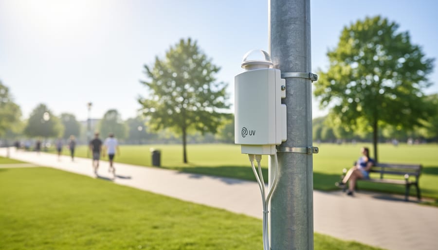
No, you should always protect the sensor and Raspberry Pi with a weatherproof enclosure rated at least IP65 for outdoor installations. The sensor itself can handle brief outdoor exposure for testing, but moisture, temperature extremes, and UV degradation of plastic components will damage unprotected electronics over time.
Which Raspberry Pi models work with Adafruit UV sensors?
All Raspberry Pi models with GPIO pins and I2C support work with Adafruit UV sensors, including Pi Zero, Pi 3, Pi 4, and Pi 5. The power consumption of these sensors is typically 1-3 mA, making them suitable even for battery-powered Pi Zero projects without draining resources.
What alternatives exist if I can’t source an Adafruit UV sensor?
The SparkFun VEML6075 and DFRobot SEN0162 offer similar UV sensing capabilities with I2C interfaces compatible with the same Raspberry Pi setup process. Generic GUVA-S12SD analog UV sensors work too but require an ADC converter since Raspberry Pi lacks native analog input pins.
These questions cover the practical aspects that determine whether your UV sensing project will succeed in real-world conditions. Accuracy expectations matter when you’re deciding if readings are trustworthy enough for your application, whether that’s a backyard weather station or a school science demonstration. Weatherproofing becomes critical the moment you move beyond desktop prototyping to permanent outdoor installations.
Compatibility concerns often prevent people from starting projects, but the low power draw and universal I2C support mean nearly any Raspberry Pi will work. If you’re sourcing components internationally or facing supply chain delays, knowing which alternative sensors use the same communication protocol saves you from redesigning your entire setup.
You have successfully integrated an Adafruit UV sensor with your Raspberry Pi, transforming a simple board into an environmental monitoring powerhouse. Through the four-step process of preparing your environment, wiring the hardware, verifying communication, and writing functional Python code, you have built a foundation for countless practical projects.
UV monitoring opens doors to applications that matter in daily life. Whether you are protecting your family from excessive sun exposure, automating outdoor equipment based on real conditions, or contributing to citizen science weather networks, your sensor now delivers actionable data. The skills you developed during this integration extend beyond UV sensing. The I2C communication protocols, GPIO wiring techniques, and Python programming patterns you practiced apply to hundreds of other sensors waiting to expand your capabilities.
Start small with data logging and visualization, then challenge yourself with more complex projects. Combine your UV sensor with temperature, humidity, and barometric pressure sensors to build a comprehensive weather station. Connect multiple sensors to create comparative datasets across different locations. Integrate machine learning to predict UV patterns and trigger automated responses.
The barrier between idea and implementation is now thinner than you might think. You have proven you can connect hardware, write code, and troubleshoot problems. Every sensor integration makes the next one easier. Your Raspberry Pi setup is ready for whatever environmental challenge interests you next. The only question remaining is which sensor you will tackle tomorrow.