

# Understanding and Using 9-Axis Sensors with Raspberry Pi
**Combine three essential motion sensors into one compact module.** A 9-axis sensor integrates an accelerometer (3 axes), gyroscope (3 axes), and magnetometer (3 axes) to track movement, orientation, and direction simultaneously. This powerhouse component enables your Raspberry Pi projects to sense acceleration, rotation, and magnetic fields—transforming simple builds into intelligent, motion-aware systems.
**Connect via I2C or SPI protocols for instant data access.** Most 9-axis sensors like the MPU-9250 or LSM9DS1 communicate through these standard interfaces, requiring just four wires to your Raspberry Pi’s GPIO pins. Enable I2C in your Raspberry Pi configuration, install Python libraries like smbus2 or CircuitPython, and you’ll start reading sensor data within minutes.
**Build projects ranging from DIY drones to gesture-controlled devices.** These sensors excel in applications requiring precise motion tracking: stabilize quadcopters, create virtual reality controllers, develop earthquake detection systems, or design wearable fitness trackers. The combined sensor data provides comprehensive spatial awareness that single-axis sensors simply cannot match.
**Choose based on accuracy needs and budget constraints.** Entry-level modules cost $5-15 and suit most hobby projects, while professional-grade sensors offer enhanced precision for demanding applications. Understanding specifications like sensitivity, noise levels, and update rates ensures you select the right sensor without overspending—beginners typically start with readily available MPU-9250 breakout boards that balance performance with affordability.
What Exactly Is a 9-Axis Sensor?
Breaking Down the Three Sensor Types
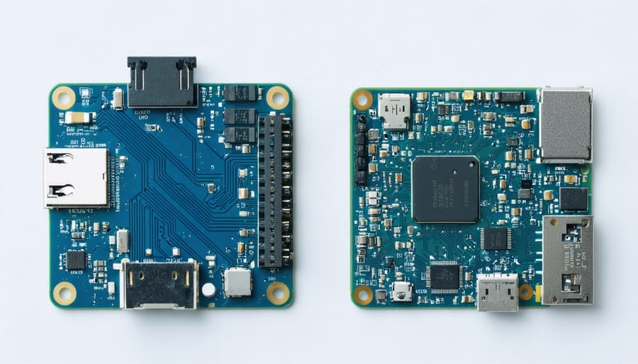
A 9-axis sensor combines three distinct sensor types, each measuring different aspects of movement and orientation. Let’s break down what each one does and why it matters for your Raspberry Pi projects.
**The Accelerometer** measures linear acceleration—essentially how fast your device is speeding up or slowing down in any direction. Think of it like feeling pushed back into your car seat when accelerating. It detects movement along three axes: forward/backward (X), left/right (Y), and up/down (Z). Beyond motion, accelerometers can also determine which way is “down” by sensing Earth’s gravity, making them perfect for detecting device orientation. You’ll find these in smartphones that rotate screens automatically and in fitness trackers counting your steps.
**The Gyroscope** tracks rotational movement—how your device is spinning or tilting around those same three axes. Imagine twisting your wrist to look at a watch; a gyroscope measures that rotation rate. While an accelerometer tells you if something moved, a gyroscope reveals how it turned. This becomes crucial for applications like drone stabilization, gaming controllers, and virtual reality headsets where precise rotation tracking makes all the difference.
**The Magnetometer** functions as a digital compass by measuring the Earth’s magnetic field. It determines which direction your device is facing relative to magnetic north, similar to a traditional compass needle. This sensor completes the picture by providing absolute directional reference, whereas accelerometers and gyroscopes only track relative changes. Combined, these three sensors work together to provide complete spatial awareness—knowing exactly where your device is, how it’s oriented, and which direction it’s facing.
Why Nine Axes Matter
A 9-axis sensor combines three different measurement systems into one compact package: an accelerometer, a gyroscope, and a magnetometer. Here’s where the “nine axes” come from—each sensor measures along three spatial dimensions (X, Y, and Z axes), giving you 3 + 3 + 3 = 9 total axes of data.
The **accelerometer** tracks linear motion and tilt by measuring acceleration forces along three axes. The **gyroscope** captures rotational movement, detecting how fast your device spins around each axis. The **magnetometer** functions like a digital compass, measuring magnetic field strength in three directions to determine orientation relative to Earth’s magnetic north.
Why does this matter? Each sensor alone has limitations. Accelerometers can’t distinguish between gravity and actual movement. Gyroscopes experience drift over time. Magnetometers can be disrupted by nearby magnetic interference. But when you combine all nine axes through **sensor fusion**—a technique that intelligently merges the data—you get remarkably accurate motion tracking that compensates for each individual sensor’s weaknesses.
This comprehensive approach enables your Raspberry Pi projects to understand position, orientation, and movement in three-dimensional space with precision that single sensors simply can’t achieve.
Popular 9-Axis Sensor Modules for Raspberry Pi
MPU-9250: The Budget-Friendly Favorite
The MPU-9250 stands as the go-to choice for makers on a budget, combining excellent performance with affordability. This compact module integrates a 3-axis gyroscope, 3-axis accelerometer, and 3-axis magnetometer (compass) all on one board, communicating via I2C or SPI protocols with your Raspberry Pi.
**Key Specifications:**
– Gyroscope range: ±250, ±500, ±1000, ±2000°/sec
– Accelerometer range: ±2g, ±4g, ±8g, ±16g
– Magnetometer resolution: 14-bit or 16-bit
– Operating voltage: 3.3V (perfect for Raspberry Pi)
– Low power consumption: ideal for portable projects
**Pros:**
– Incredibly affordable (typically $5-$15)
– Well-documented with extensive community support
– Compact size fits tight project spaces
– Easy Python library integration
**Cons:**
– Magnetometer requires calibration for accurate readings
– Can be sensitive to electromagnetic interference
– Less precise than industrial-grade alternatives
The MPU-9250’s balance of features and price makes it perfect for learning projects, drone stabilization, robotics orientation tracking, and motion-controlled devices. While it may not match professional-grade sensors, it delivers impressive results for educational and hobby applications.
BNO055: The Smart Sensor with Built-In Fusion
The BNO055 stands out as the “smart” option in the 9-axis sensor world. Unlike the MPU-9250, this Bosch sensor includes a dedicated ARM Cortex-M0 processor that handles sensor fusion calculations internally. This means it outputs ready-to-use orientation data—no complex programming required on your Raspberry Pi.
For beginners, the BNO055 is incredibly appealing. Instead of wrestling with quaternions and Kalman filters, you simply request absolute orientation angles and get accurate results immediately. The sensor delivers orientation in degrees, making it perfect for robotics projects, camera gimbals, or VR tracking systems where you need reliable data without the learning curve.
The trade-off? Cost and availability. The BNO055 typically runs $20-30, roughly double the MPU-9250’s price. You’re also locked into Bosch’s fusion algorithm with limited customization options.
**When it’s worth it:** Choose the BNO055 if you’re prototyping quickly, teaching sensor concepts, or building projects where programming time matters more than component cost. The plug-and-play nature makes it ideal for educational settings and rapid development.
**When to skip it:** Advanced users wanting full control over fusion algorithms or working on cost-sensitive production runs might prefer implementing their own solutions with cheaper IMUs.
LSM9DS1: The Precision Option
The LSM9DS1 stands out as the go-to choice when your project demands exceptional accuracy and stability. This ST Microelectronics sensor delivers 16-bit resolution across all nine axes, providing remarkably precise measurements that make it ideal for applications where even small errors can impact performance.
What sets the LSM9DS1 apart is its sophisticated sensor fusion capabilities and low noise output. The accelerometer offers selectable full-scale ranges from ±2g to ±16g, while the gyroscope provides options from ±245 to ±2000 degrees per second. The magnetometer operates with a resolution of 0.14 milligauss per digit, enabling highly accurate compass readings.
You’ll find the LSM9DS1 excelling in projects requiring precise orientation tracking, such as drone flight controllers, camera stabilization systems, and robotics applications where accurate positioning is critical. Its superior performance also makes it perfect for educational projects teaching sensor fusion algorithms and Kalman filtering.
The sensor communicates via both I2C and SPI protocols, offering flexibility in your Raspberry Pi setup. While it typically costs slightly more than the MPU-9250, around $10-15, the investment pays off when precision is non-negotiable for your application’s success.
How to Connect a 9-Axis Sensor to Your Raspberry Pi
What You’ll Need
To get started with your 9-axis sensor project, you’ll need a few essential components. First, grab a **Raspberry Pi** (any model with GPIO pins will work, though Pi 3 or 4 is recommended) and a **9-axis IMU sensor board** like the MPU-9250 or BNO055. You’ll also need **jumper wires** (female-to-female work best) for connections and a **breadboard** for prototyping.
Make sure you have an SD card with Raspberry Pi OS installed and internet access for downloading necessary libraries. Basic tools like a small screwdriver set can help if you’re mounting the sensor in a project enclosure.
**Optional items** include a **protective case** to secure your Raspberry Pi, an **external power supply** for stable voltage, and **mounting hardware** if you’re building a drone or robotics project.
Wiring Your Sensor
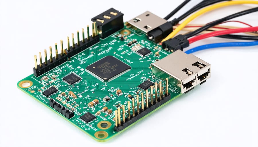
Connecting your 9-axis sensor to the Raspberry Pi is straightforward using the I2C interface. Most modules, like the MPU-9250 or BNO055, feature a standard four-pin configuration that makes setup simple even for beginners.
Start by identifying the four pins on your sensor module: VCC (power), GND (ground), SDA (data), and SCL (clock). On your Raspberry Pi, you’ll connect these to the corresponding GPIO pins. Connect VCC to pin 1 (3.3V)—never use 5V as this can damage the sensor. Ground (GND) goes to pin 6. The SDA pin connects to GPIO 2 (physical pin 3), and SCL connects to GPIO 3 (physical pin 5).
For reliable connections, use quality female-to-female jumper wires and ensure they’re firmly seated on both the sensor and GPIO pins. If you’re planning a permanent installation, consider soldering header pins to your sensor module for more stable connections.
**Pro tips for success:** Keep your wiring neat and organized—this makes troubleshooting much easier. Avoid running I2C wires parallel to power cables for long distances, as this can introduce interference. If your sensor has additional pins like INT (interrupt) or AD0 (address selection), you can leave them disconnected for basic projects.
Before powering up, double-check your connections against this guide. A misconnected power pin could damage your sensor or Raspberry Pi. Once verified, you’re ready to enable I2C communication and start reading sensor data!
Enabling I2C on Raspberry Pi
Before connecting your 9-axis sensor, you’ll need to enable the I2C interface on your Raspberry Pi. This communication protocol allows your Pi to “talk” to the sensor and retrieve motion data.
Start by opening a terminal and typing `sudo raspi-config`. Navigate to **Interface Options**, then select **I2C** and choose **Yes** to enable it. Reboot your Pi with `sudo reboot` to apply the changes.
Once restarted, verify I2C is working by installing the necessary tools: `sudo apt-get install i2c-tools`. Then run `sudo i2cdetect -y 1` to scan for connected devices. You should see a hexadecimal address (commonly 0x68 or 0x69 for most 9-axis sensors) displayed in the grid—this confirms your sensor is properly detected and ready for programming!
Getting Your First Readings: A Beginner’s Tutorial
Installing the Necessary Libraries
Before you can start reading data from your 9-axis sensor, you’ll need to install a few Python libraries on your Raspberry Pi. Don’t worry—this process is straightforward and takes just a few minutes!
First, ensure your system is up to date by opening a terminal and running:
“`
sudo apt-get update
sudo apt-get upgrade
“`
Next, install the essential `smbus` library, which enables I2C communication between your Raspberry Pi and the sensor:
“`
sudo apt-get install python3-smbus i2c-tools
“`
For many popular 9-axis sensors like the MPU-9250 or BNO055, you’ll want sensor-specific libraries. Install the Adafruit CircuitPython bundle, which includes drivers for numerous sensors:
“`
pip3 install adafruit-circuitpython-bno055
“`
If you’re using an MPU-9250, try the community-maintained library:
“`
pip3 install mpu9250-jmdev
“`
Verify your installation by running `i2cdetect -y 1` to scan for connected devices. You should see your sensor’s address displayed in the grid. With these libraries installed, you’re ready to start collecting motion data from your 9-axis sensor!
Your First Python Script
Now that your sensor is wired up, let’s bring it to life with Python! We’ll use the popular `mpu9250-i2c` library to communicate with your 9-axis sensor and display real-time data from the accelerometer, gyroscope, and magnetometer.
First, install the necessary library by opening your Raspberry Pi terminal and typing:
“`bash
pip3 install mpu9250-i2c
“`
Here’s a complete, beginner-friendly script to get you started:
“`python
import time
from mpu9250_i2c import MPU9250
# Initialize the sensor with default I2C address (0x68)
sensor = MPU9250(
address_ak=0x0C, # Magnetometer address
address_mpu_master=0x68, # MPU address
bus=1 # I2C bus number (usually 1 on Raspberry Pi)
)
# Configure the sensor for optimal performance
sensor.configure()
print(“Reading 9-axis sensor data… Press Ctrl+C to stop\n”)
try:
while True:
# Read accelerometer data (measures acceleration in m/s²)
accel_data = sensor.readAccelerometerMaster()
print(f”Accelerometer – X: {accel_data[0]:.2f}, Y: {accel_data[1]:.2f}, Z: {accel_data[2]:.2f}”)
# Read gyroscope data (measures rotation in degrees/second)
gyro_data = sensor.readGyroscopeMaster()
print(f”Gyroscope – X: {gyro_data[0]:.2f}, Y: {gyro_data[1]:.2f}, Z: {gyro_data[2]:.2f}”)
# Read magnetometer data (measures magnetic field strength)
mag_data = sensor.readMagnetometerMaster()
print(f”Magnetometer – X: {mag_data[0]:.2f}, Y: {mag_data[1]:.2f}, Z: {mag_data[2]:.2f}\n”)
time.sleep(0.5) # Wait half a second between readings
except KeyboardInterrupt:
print(“\nSensor reading stopped”)
“`
**What’s happening here?** The script initializes communication with your sensor, then continuously reads data from all three components in a loop. Each sensor returns three values representing the X, Y, and Z axes. The accelerometer shows movement and tilt, the gyroscope tracks rotation speed, and the magnetometer detects magnetic north like a digital compass. Run this script and try moving your sensor around to see the values change in real-time!
Understanding the Data Output
When your 9-axis sensor sends data to your Raspberry Pi, you’ll receive three sets of values that need interpretation. The accelerometer outputs linear acceleration in meters per second squared (m/s²) or G-forces, typically ranging from -2G to +2G for stationary devices. The gyroscope measures rotational velocity in degrees per second (°/s) or radians per second, with values near zero when still. The magnetometer provides magnetic field strength in microTeslas (µT) or Gauss, showing Earth’s magnetic field at around 25-65 µT depending on location.
Normal readings for a stationary sensor show accelerometer values near 0, 0, and 9.8 m/s² (or 0, 0, 1G) on the X, Y, and Z axes respectively—that’s gravity! Gyroscope values should hover around zero with minimal drift, while magnetometer readings point toward magnetic north and remain relatively stable. These raw values need calibration to account for sensor bias and environmental interference, especially for the magnetometer near electronics.
Real-World Projects You Can Build
Motion-Activated Camera System
A motion-activated camera system leverages your 9-axis sensor to create intelligent surveillance that responds to specific movements and orientations. By mounting the sensor on a pan-tilt mechanism with your Raspberry Pi camera, you can detect when objects move in particular directions or when the camera itself is tilted or rotated unexpectedly.
The accelerometer tracks sudden movements, the gyroscope monitors rotation speed, and the magnetometer provides directional awareness. Program your system to trigger recording only when detecting human-like motion patterns—filtering out pets or swaying branches. You can set it to alert you via email when detecting suspicious activity or automatically pan to follow moving objects.
This project pairs well with other sensing technologies like LiDAR scanning projects for enhanced spatial awareness. Start by mounting your hardware, then write Python code using sensor fusion algorithms to distinguish between normal and unusual movement patterns. The result is a smart security system far more sophisticated than basic motion detectors.
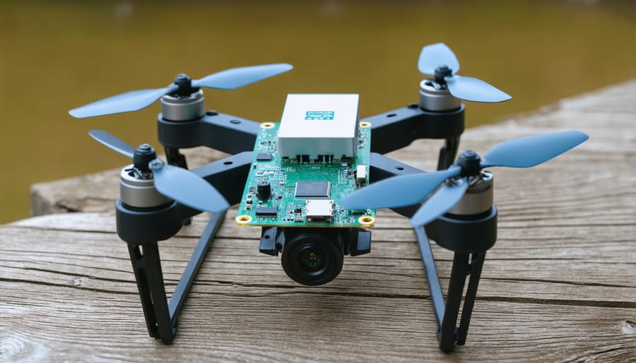
DIY Drone Flight Controller
Building your own drone flight controller is an exciting way to put 9-axis sensor data to work! The accelerometer tracks your quadcopter’s speed changes, the gyroscope monitors rotation rates, and the magnetometer provides directional heading—all crucial for stable flight. By combining these readings through sensor fusion algorithms, your Raspberry Pi can calculate the drone’s precise orientation in real-time and make instant adjustments to keep it level.
Start with a simple stabilization project: mount your 9-axis sensor on a basic quadcopter frame and write code to read orientation data. Your flight controller algorithm will compare the current tilt angle against your desired position, then adjust motor speeds accordingly to maintain balance. Many hobbyists pair their controllers with wireless communication modules for remote piloting. Popular Python libraries like `smbus` and `mpu6050-raspberrypi` simplify sensor integration, letting you focus on tuning your control loops for smooth, responsive flight.
VR Head Tracking Device
Building an immersive VR head-tracking system doesn’t require expensive hardware—a 9-axis sensor paired with your Raspberry Pi can deliver smooth, responsive motion tracking at a fraction of commercial costs. The sensor’s accelerometer, gyroscope, and magnetometer work together to capture every head movement with precision, translating real-world rotations into virtual camera movements.
Start by mounting your 9-axis sensor securely to a lightweight VR headset frame or Google Cardboard setup. Connect it to your Raspberry Pi via I2C, then use sensor fusion libraries like Madgwick or Kalman filters to combine the three sensor inputs into accurate orientation data. This eliminates drift and jitter common in single-sensor solutions.
For best results, calibrate your magnetometer away from magnetic interference and implement complementary filtering in your code. Stream the orientation data to VR applications like Unity or Godot engines over WiFi for wireless freedom. With proper calibration, you’ll achieve head tracking that rivals commercial systems, perfect for educational VR projects or custom gaming experiences.
Smart Home Gesture Controller
Transform your Raspberry Pi into an intuitive smart home controller using a 9-axis sensor to detect hand gestures. This project lets you control lights, adjust thermostats, or trigger automated routines with simple hand movements—no physical contact required.
Start by mounting your 9-axis sensor on a wearable wristband or positioning it in a fixed location where it can track hand movements. The accelerometer detects motion direction, the gyroscope captures rotation angles, and the magnetometer provides orientation reference. Together, these create a comprehensive gesture profile.
Program your Raspberry Pi to recognize specific gesture patterns. For example, a clockwise circular motion could increase brightness, while a swipe left might turn off devices. Use Python libraries to set motion thresholds that distinguish intentional gestures from accidental movements. Store gesture templates as arrays of sensor readings for pattern matching algorithms.
Integration with smart home platforms is straightforward. Connect your gesture controller to devices via MQTT, Wi-Fi, or RF communication protocols. You can even combine multiple gestures into sequences for complex commands, like dimming lights and activating your entertainment system simultaneously.
This hands-free control system is particularly useful for accessibility applications, making smart home technology more inclusive for users with mobility challenges.
Troubleshooting Common Issues
Sensor Not Detected
If your Raspberry Pi isn’t detecting the 9-axis sensor, start by verifying your I2C connection. Run `sudo i2cdetect -y 1` in the terminal to scan for connected devices. If nothing appears, double-check your wiring—ensure SDA connects to GPIO 2, SCL to GPIO 3, VCC to 3.3V, and GND to ground. Loose jumper wires are common culprits!
Address conflicts can occur if multiple I2C devices share the same address. Check your sensor’s datasheet for its default address (often 0x68 or 0x69) and verify it doesn’t clash with other connected devices. Some sensors have solder bridges or jumpers to change addresses.
Still having issues? Confirm I2C is enabled by running `sudo raspi-config`, navigating to Interface Options, and enabling I2C. After enabling, reboot your Pi and try detection again. This simple step resolves most detection problems for beginners!
Noisy or Erratic Readings
Noisy or erratic readings from your 9-axis sensor can frustrate even experienced makers. Common culprits include electromagnetic interference from nearby motors or power supplies, poor connections on breadboards, inadequate power supply regulation, and sensor vibrations. Environmental factors like temperature fluctuations can also affect accuracy.
To combat noise, start with proper physical setup: use short, twisted wires for I2C connections, add a decoupling capacitor (0.1µF) near the sensor’s power pins, and ensure stable power delivery. Software filtering techniques are equally important. Implement a simple moving average filter by storing the last 5-10 readings and calculating their mean. For more sophisticated smoothing, try a complementary filter or low-pass filter—most sensor libraries include built-in options. Calibration routines can also significantly improve data quality by accounting for sensor-specific offsets. Remember, some noise is inevitable; the goal is reducing it to acceptable levels for your specific application.
Calibration Tips
Calibration ensures your 9-axis sensor delivers accurate readings, especially for the magnetometer, which is highly sensitive to magnetic interference from nearby electronics, metal objects, and even your Raspberry Pi itself. Without calibration, you’ll experience drifting orientation data and unreliable compass readings.
**Magnetometer calibration** involves rotating your sensor in a figure-eight pattern through all orientations while recording data. This maps out magnetic distortions in your environment. Most sensor libraries include calibration functions that calculate offset values to compensate for these distortions.
For **accelerometers and gyroscopes**, calibration is simpler—place your sensor on a flat, stable surface and run the calibration routine. The sensor establishes its zero reference points for accurate tilt and rotation measurements.
**Pro tip:** Recalibrate whenever you change your sensor’s physical mounting location or add new components nearby. Store calibration values in a configuration file so you don’t need to repeat the process every time your Raspberry Pi restarts. Most Python libraries like `mpu9250-jmdev` and `Adafruit_CircuitPython` provide straightforward calibration examples to get you started quickly.
9-axis sensors offer an incredible combination of versatility, affordability, and accessibility that make them perfect for Raspberry Pi enthusiasts at any skill level. Whether you’re tracking motion for a robotics project, building a drone stabilization system, or creating interactive art installations, these compact sensors provide professional-grade orientation data without breaking the bank.
The beauty of working with 9-axis sensors lies in their straightforward integration process. With just a few wires and some basic Python code, you can unlock powerful motion sensing capabilities that were once reserved for expensive commercial applications. The thriving Raspberry Pi community has created extensive libraries and documentation that make getting started easier than ever.
Ready to dive in? Start with a simple tilt detection project to familiarize yourself with the data outputs, then gradually explore more complex sensor integration projects as your confidence grows. The official Raspberry Pi forums, GitHub repositories, and dedicated sensor manufacturer documentation provide excellent resources for troubleshooting and advanced techniques. Remember, every expert started as a beginner—your first 9-axis sensor project is just the beginning of an exciting journey into motion sensing and embedded systems!