

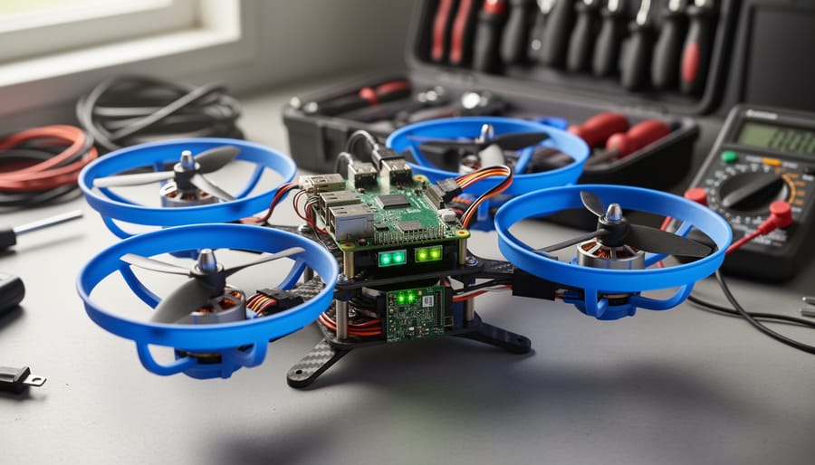
Building a Raspberry Pi quadcopter gives you a fully functional drone for $200-350 that you can program, customize, and fly within a weekend. Unlike commercial drones with locked-down firmware or expensive flight controllers that cost $150 alone, this project uses the Raspberry Pi as both the flight controller and computing brain, letting you access every line of code and sensor reading while learning real-world robotics and flight dynamics.
The appeal goes beyond cost savings. You’ll wire your own power distribution system, calibrate ESCs (electronic speed controllers) that translate software commands into motor speeds, and write or modify Python scripts that keep your quadcopter stable in the air. If you’ve tackled first robot kits you already understand GPIO basics and can now apply that knowledge to three-dimensional flight control.
This guide walks you through every component choice, from selecting motors with the right KV rating to picking a frame that balances weight and durability. You’ll see wiring diagrams that prevent the most common beginner mistakes (reversed motor directions, incorrect ESC connections), step-by-step calibration procedures for gyroscopes and accelerometers, and pre-flight checks that keep your build airborne and safe. Whether you want FPV camera integration, GPS waypoint navigation, or obstacle avoidance using ultrasonic sensors, building your own Pi-powered quadcopter gives you the foundation to implement any feature you can code.
Parts, Tools, and Materials You’ll Need
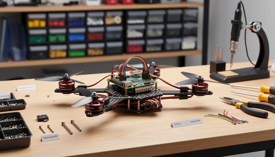
Building a Raspberry Pi quadcopter requires careful selection of components that work together seamlessly. Here’s everything you’ll need, organized by system, with guidance on where to allocate your budget wisely.
Flight Controller Components
Your Raspberry Pi serves as the brain of this quadcopter. The Raspberry Pi 4 Model B (2GB or 4GB) offers the best balance of processing power and cost for 2026 builds. The Zero 2 W works if you’re chasing weight savings, but its single-core architecture struggles with real-time flight calculations. Don’t cheap out here, erratic flight behavior often traces back to underpowered processors.
You’ll also need a compatible sensor module like the Navio2 or similar IMU shield that provides gyroscope, accelerometer, and barometer data. These typically connect via GPIO and cost £60-90. Verify your chosen flight software supports your sensor board before purchasing.
Frame and Motors
A 450mm carbon fiber frame kit (£25-40) provides the structural foundation. Carbon fiber resists crashes better than plastic alternatives while keeping weight manageable. The kit should include arms, body plates, and mounting hardware.
For motors, 920KV to 1000KV brushless outrunners matched to your frame size deliver reliable thrust. You need four identical motors (£40-60 for the set). Lower KV ratings improve flight time; higher ratings increase agility. Beginners should favor stability over performance.
Propellers matter more than most builders realize. Get 9-10 inch props matched to your motor specifications, several sets, because you will break them. Self-tightening designs (£8-12 per set of four) prevent mid-flight loosening.
Power System
Electronic Speed Controllers (ESCs) regulate motor speed. Choose 30A ESCs with BEC (£40 for four) that support your motor current draw with headroom. SimonK or BLHeli firmware ensures responsive throttle control.
A 3S or 4S LiPo battery (3000-5000mAh, £30-60) powers everything. Higher capacity extends flight time but adds weight. Invest in a quality balance charger (£25-45) that prevents dangerous overcharging and monitors cell voltage.
Don’t forget a power distribution board (£8-15) to route battery power cleanly to all four ESCs.
Sensors and Control
Beyond the IMU shield, you’ll need an RC receiver compatible with your transmitter (£20-35). FlySky or FrSky systems work reliably for beginners. Some builders prefer Bluetooth modules for smartphone control, though dedicated RC offers better range and fail-safe options.
Essential Tools
Soldering iron and solder (£25-40 for decent temperature-controlled unit), hex drivers for frame assembly, wire strippers, heat shrink tubing, electrical tape, and zip ties for cable management round out your toolkit. A multimeter (£15-20) proves invaluable for diagnosing electrical issues during assembly and troubleshooting.
Budget £250-400 total depending on component quality choices. Saving money on the frame or props makes sense; cutting corners on the battery or ESCs creates safety hazards.
Safety Precautions and Pre-Flight Warnings
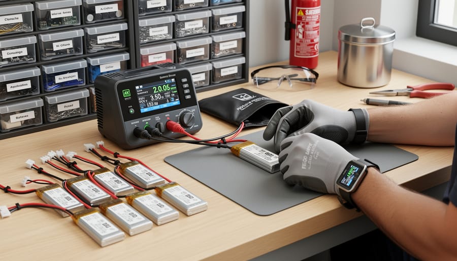
Before powering up your quadcopter for the first time, understand that you’re building a machine with spinning blades and volatile energy storage. Skipping safety steps can damage your project, injure you, or create legal headaches.
LiPo batteries demand respect. Never charge them unattended or on flammable surfaces, use a fireproof charging bag and keep a smoke detector nearby. Store batteries at half charge in a cool, dry location, and inspect them before each use for swelling, punctures, or damage. A compromised LiPo can catch fire or explode. If a battery puffs up or smells strange, stop using it immediately and dispose of it properly at a battery recycling center.
Propellers spin fast enough to cut skin and break bones. Remove them completely during all bench testing, software configuration, and motor calibration. Only attach propellers when you’re ready for an actual flight test in an open space. Wear safety glasses during flight tests, and never reach toward a powered quadcopter.
Set up your workspace with adequate ventilation and a non-conductive mat for soldering. Keep a fire extinguisher rated for electrical fires within reach. When connecting power for the first time, have the battery disconnected until you’ve triple-checked all wiring against your diagram. One reversed polarity connection can fry your Raspberry Pi or ESCs instantly.
Check 2026 drone regulations for your area before flying. Most regions require registration for quadcopters above a certain weight, restrict flight near airports and populated areas, and mandate line-of-sight operation. Using reliable test equipment during assembly helps catch electrical issues before they escalate into safety problems.
If something smokes, sparks, or smells burnt during testing, disconnect the battery immediately and don’t reconnect power until you’ve identified the fault. Rushing past a warning sign turns a fixable mistake into destroyed components or worse.
Preparing Your Raspberry Pi Flight Controller
Installing Flight Control Software
Start by installing ArduPilot, the most mature open-source flight control software that runs on Raspberry Pi with the Navio2 autopilot shield or compatible HATs. Connect to your Pi via SSH and update the system with `sudo apt update && sudo apt upgrade`. Clone the ArduPilot repository from GitHub using `git clone `, then navigate to the ArduCopter directory. Run the installation script `Tools/environment_install/` to pull in all dependencies, which takes 10-15 minutes.
After installation completes, compile the code for your specific board using `./waf configure –board navio2` followed by `./waf copter`. This builds the flight controller executable tailored to your hardware. Install required Python libraries for sensor communication with `pip3 install pymavlink dronekit smbus2`, which handle telemetry data and I2C sensor interfaces. The GPIO setup follows similar principles to other Pi projects but requires real-time access.
Create a systemd service to launch ArduPilot on boot by copying the example service file to `/etc/systemd/system/` and enabling it with `sudo systemctl enable arducopter`. Edit the default parameters file at `/etc/default/arducopter` to set your frame type, sensor orientation, and initial PID values. Don’t modify advanced parameters yet, stick with tested defaults until you’ve completed calibration.
Configuring Sensor Integration
The Raspberry Pi controls your quadcopter by reading data from sensors dozens of times per second. You’ll need to enable I2C and SPI protocols so the Pi can communicate with your IMU, which bundles the gyroscope and accelerometer into one chip.
Open the terminal on your Pi and run `sudo raspi-config`. Navigate to Interfacing Optionsthen enable both I2C and SPI. Reboot when prompted.
After restarting, connect your IMU sensor board to the correct GPIO pins, typically SDA to GPIO 2, SCL to GPIO 3, with 3.3V power and ground. If your barometer uses I2C, connect it to the same bus using different address pins.
Verify communication by running `sudo i2cdetect -y 1` in the terminal. You should see a hex address appear in the grid, commonly 0x68 for MPU-6050 IMUs or 0x77 for BMP280 barometers. No address means loose wiring or incorrect pin connections.
Install the sensor libraries your flight software requires, usually through pip commands like `pip3 install smbus2` or the manufacturer’s Python package. Run the test script included with your flight control software to confirm you’re receiving live sensor readings before moving to the next assembly stage.
Assembling the Quadcopter Frame and Motors
Start by laying out all frame components on a clean workspace and identifying each arm, the center plate, and mounting hardware. Most quadcopter frames come as kits with carbon fiber or aluminum arms, inspect each piece for cracks or defects before assembly. If your frame requires assembly, attach the four arms to the center plate using the provided screws, ensuring each arm extends at exactly 90 degrees from its neighbors. A symmetrical frame is critical for stable flight, so measure diagonally from motor mount to motor mount; both diagonal measurements should match within 2mm.
Motor orientation matters more than most beginners realize. Each quadcopter uses two clockwise (CW) and two counter-clockwise (CCW) motors positioned in an X configuration. Standard layouts place CW motors on the front-right and rear-left arms, with CCW motors on front-left and rear-right. Check your motors carefully, CW and CCW versions often look identical but have opposite thread directions on their shafts. Mount each motor to its designated arm using the included screws, making sure the motor shaft points directly upward and the motor sits flush against the mounting plate. Tighten screws in a star pattern to distribute pressure evenly and prevent warping the motor bell.
- Lay out all frame parts and verify no cracks or missing hardware
- Attach four arms to center plate at precise 90-degree intervals
- Measure both diagonals to confirm frame symmetry (within 2mm)
- Identify which motors are CW vs CCW by checking shaft threads
- Mount front-right motor (CW) using star-pattern tightening
- Mount rear-left motor (CW) in the same manner
- Mount front-left motor (CCW) to complete the pattern
- Mount rear-right motor (CCW) for final motor position
- Secure one ESC per arm using zip ties or adhesive pads
- Route ESC power wires toward center plate along underside of arm
- Bundle and secure signal wires to avoid propeller strike zones
- Verify all motors spin freely without hitting frame or wires
Position each ESC on its corresponding arm, close to the motor but far enough from the center to allow airflow for cooling. Use zip ties or double-sided foam pads to secure ESCs, avoid hot glue, which makes future repairs difficult. Route the three motor wires from each ESC directly to its motor with minimal excess length, then run power wires along the underside of the arm toward the center plate where your power distribution board will sit. Keep all signal wires that will connect to your Raspberry Pi grouped together and routed away from propeller paths.
Cable management separates reliable quadcopters from troublesome ones. Propellers spinning at several thousand RPM will destroy any wire in their path, so bundle loose cables tightly against the frame using additional zip ties. Leave just enough slack in motor wires to allow for future maintenance, but eliminate any loops or drooping sections. Before proceeding, manually spin each motor by hand to verify nothing catches or rubs, you should feel smooth, unrestricted rotation on all four motors.
Wiring the Power Distribution and ESCs
Start by disconnecting your battery and keeping it away from the workspace. This electrical phase carries the highest risk of short circuits, so you’ll work methodically and double-check every connection before applying power.
The power distribution board (PDB) serves as the central hub. Solder the main battery leads, thick red (positive) and black (negative) wires, to the designated pads on the PDB, typically marked with “+” and “−” symbols or “BAT+” and “BAT−”. Use a soldering iron set to 350-400°C and work quickly to avoid overheating the board. If your PDB includes an XT60 connector pre-installed, you can skip soldering the battery leads directly and instead connect via the plug.
Next, solder power input wires from each of your four ESCs to the PDB. Each ESC has a thick red and black wire pair for power input; these connect to the PDB’s distribution pads, which provide regulated voltage to all four ESCs simultaneously. Space the ESC connections evenly around the PDB to balance weight. Strip 3-4mm of insulation from each wire, tin the exposed copper with solder, then attach to the pads. Hold each joint for two seconds after the solder flows to ensure a solid bond.
Now connect each ESC’s three motor wires to its corresponding motor. These wires typically lack polarity markings because they’re three-phase AC, but the connection order determines rotation direction. Connect any two wires from the ESC to any two motor terminals initially; you’ll swap one pair later if the motor spins the wrong direction during testing.
The ESC signal wires, usually a three-pin servo connector with brown/black (ground), red (5V), and white/yellow (signal), connect to your Raspberry Pi’s GPIO pins. Connect ground to a Pi ground pin, skip the 5V wire entirely (the Pi cannot safely power ESCs this way), and connect the signal wire to the designated GPIO pin for that motor. For a standard quadcopter setup, use GPIO pins 17, 18, 22, and 23 for motors one through four. Consult your flight control software documentation for the exact pin mapping.
Bundle signal wires together using zip ties or braided cable sleeving, routing them along the frame arms away from spinning propellers. Keep power wires separate from signal wires where possible to reduce electrical noise that can interfere with sensor readings. Secure all connections with a dab of hot glue after verifying they work correctly, this prevents vibration from loosening wires during flight.
Mounting and Connecting Sensors
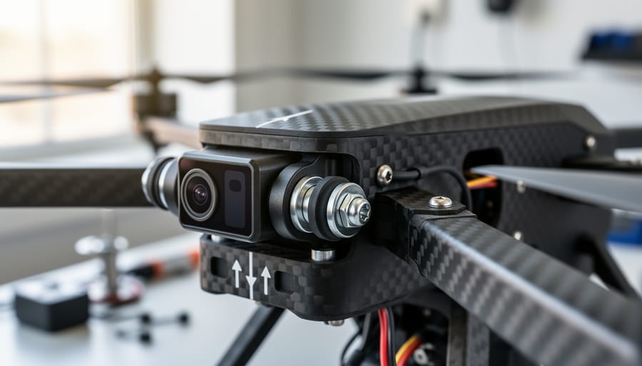
Sensor placement isn’t just about making things fit, it directly affects how well your quadcopter can detect and correct for movement. The IMU (inertial measurement unit) must sit as close to the center of gravity as possible, typically on top of the Raspberry Pi or on a dedicated mounting plate between the arms. Mount it flat and level with the arrow marking pointing toward the front of the frame. Even a few degrees of tilt will throw off your accelerometer readings and cause drift.
Secure the IMU using foam tape or rubber standoffs rather than hard-mounting it directly to the frame. This dampens vibrations from the motors that would otherwise corrupt sensor data. If you’re adding a barometer for altitude hold, mount it away from direct propwash and ESC heat, which can create false pressure readings.
For I2C connections, run four wires from the sensor to your Raspberry Pi: VCC to 3.3V, GND to ground, SDA to GPIO2, and SCL to GPIO3. Keep these wires short and twisted together to reduce electrical interference. SPI sensors need additional connections for CS (chip select) and MISO/MOSI data lines, consult your specific sensor’s pinout diagram. Many of these principles mirror robot building basics just applied to flight.
Before bolting everything down permanently, power up the Pi and run `i2cdetect -y 1` in the terminal. You should see your sensor’s address appear in the output grid, typically 0x68 for common IMUs. No detection means checking your wiring and ensuring I2C is enabled in raspi-config. Once confirmed, run your flight software’s sensor test routine to verify all axes report changing values when you tilt the frame.
Setting Up Your Remote Control System
Your quadcopter needs a reliable way to receive flight commands, whether from a traditional RC transmitter or a modern smartphone controller. The most dependable option remains a dedicated 2.4GHz RC system with separate transmitter and receiver, as these provide lower latency and better range than wireless alternatives.
Start by binding your transmitter to the receiver following the manufacturer’s specific procedure. Most systems require holding a bind button on the receiver while powering it on, then entering bind mode on the transmitter. The receiver’s LED will change from blinking to solid when successfully paired. Complete this step before any wiring to confirm the hardware works.
Connect the receiver to your Raspberry Pi through the GPIO pins. Standard PWM receivers have individual channel outputs (typically channels 1-4 for roll, pitch, throttle, and yaw) that connect directly to GPIO pins you’ll designate in your flight software. Each channel wire has three connections: signal (usually white or yellow), power (red), and ground (black or brown). Connect signal wires to separate GPIO pins, and share common 5V power and ground lines from the Pi’s header. PPM or SBUS receivers simplify wiring by combining all channels into a single signal wire, reducing GPIO usage.
Configure your flight controller software to read the correct GPIO pins and map each channel to its flight function. Typical mapping assigns channel 1 to roll (right stick left/right), channel 2 to pitch (right stick forward/back), channel 3 to throttle (left stick up/down), and channel 4 to yaw (left stick left/right). Test each input by moving sticks and watching values in your configuration software, ensuring full range (usually 1000-2000 microseconds) and centered neutral positions around 1500 microseconds.
For smartphone control via Wi-Fi, install companion apps that communicate with your flight software through UDP packets. These work for line-of-sight flying and testing but introduce latency and rely on your Pi’s Wi-Fi stability. Reserve smartphone control for stationary experiments rather than dynamic flight until you’ve validated reliability in your specific environment.
Calibrating and Testing Before First Flight
Before you even think about attaching propellers, you need to verify that every system responds correctly. Skipping these checks is how quadcopters flip immediately on takeoff or fly uncontrollably into walls. Set aside at least an hour for this process the first time, rushing through calibration causes most beginner crashes.
Start with sensor calibration. Place your quadcopter on a completely level surface and run the IMU calibration routine in your flight control software. The accelerometer needs to establish what “level” means, and the gyroscope must zero out its drift. Don’t touch the frame during this process. Most calibration scripts take 30-60 seconds and will indicate completion. If calibration fails repeatedly, check that your sensors are firmly mounted without vibration and that no wires are creating mechanical stress on the sensor board.
Next comes ESC calibration, which teaches each ESC the throttle range of your transmitter. With the battery disconnected and propellers still off, set your transmitter throttle to maximum. Power up the Raspberry Pi and run the ESC calibration script, then connect the battery. You’ll hear a series of beeps from each motor. When the beeping pattern changes, drop the throttle to minimum. The ESCs confirm calibration with another beep sequence. This step prevents throttle mismatch where motors spin at different speeds for the same command.
Now test motor spin direction without propellers. Apply gentle throttle, each motor should spin. Motors on opposite corners should rotate the same direction. Front-right and back-left spin clockwise; front-left and back-right spin counter-clockwise. If any motor spins the wrong way, swap any two of its three ESC wires. Wrong motor direction means your quadcopter will spin violently instead of lifting straight up.
Verify control surface response next. With everything powered and the transmitter bound, move the right stick forward (pitch). The front motors should speed up slightly while rear motors slow down, the quad tilts forward without propellers. Pull the stick back and the opposite happens. Roll and yaw controls should produce similar logical responses. If controls are reversed, fix the channel mapping in your flight software before proceeding.
Run through this complete pre-flight checklist every time before attaching propellers:
- Sensor readings show stable, reasonable values (no erratic IMU data)
- All four motors spin in the correct direction
- Throttle increases motor speed smoothly without jumps
- Pitch, roll, and yaw controls produce expected motor responses
- Battery voltage checks confirm full charge above minimum threshold
- Emergency cutoff switch immediately stops all motors
Test your failsafe by turning off the transmitter while the quad is powered. Motors should stop within one second. If they keep spinning, your receiver isn’t configured for failsafe mode, fix this before any flight attempt. A failsafe failure means a runaway drone if you lose signal.
Finally, check physical security. Shake the frame gently and listen for rattles. Tug each wire connection. Verify the battery is strapped down firmly. A vibrating sensor mount or loose connection will cause erratic behavior that no amount of software tuning can fix.
First Flight: Hover Test and Tuning
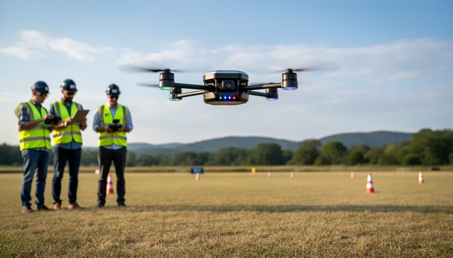
Find an open outdoor area with at least 20 feet of clearance in all directions, free from people, pets, and obstacles. Check the battery is fully charged, weather conditions are calm (less than 5 mph wind), and you have a clear escape plan if the quadcopter behaves erratically. Place the quadcopter on flat ground, arm the motors using your transmitter, and slowly increase throttle until it lifts a few inches off the ground.
Your first hover will reveal how well balanced and calibrated everything is. The quadcopter should rise steadily and hold position without drifting significantly. If it immediately tips to one side, cut throttle and land. Check that all motors are spinning correctly and the frame is level. If it oscillates rapidly, bouncing up and down or shaking side to side, your PID gains are too high. Reduce the proportional gain by 20% and try again.
Drift in one direction usually means the frame isn’t balanced or motors have different thrust outputs. Land, recheck motor mounting angles and ensure all propellers are undamaged and properly tightened. You can compensate slightly with trim settings on your transmitter, but excessive trim means a physical problem needs fixing.
Sluggish response to control inputs indicates gains are too low. The quadcopter should react within a fraction of a second when you move the sticks. Increase the proportional gain by 10-15% between short test flights until you achieve crisp response without introducing oscillation. The derivative gain smooths out corrections; increase it if the quadcopter overshoots when you center the sticks.
Keep initial flights under 30 seconds to preserve battery for multiple attempts. After three to five successful hovers where the quadcopter lifts smoothly, holds steady for 10 seconds, and lands controllably, you can extend flight time and practice gentle forward, backward, and lateral movements. Record your gain settings after each adjustment so you can revert if changes make things worse. Most builders need 5-10 test flights to dial in stable hover before progressing to dynamic flight.
Verifying Success and Next Steps
You’ve done the hard work of assembly, wiring, and calibration. Now it’s time to verify your quadcopter actually works as intended before attempting anything ambitious.
Start with a stable hover test in an open area free from obstacles. Your quadcopter should maintain a steady hover between knee and waist height for at least 30 seconds without drifting more than a meter in any direction. If it wobbles excessively or pulls to one side, you need more PID tuning before proceeding. Throttle up slowly and confirm all four motors respond evenly, any motor lagging behind signals a wiring or ESC issue worth investigating on the ground.
Test each control input individually. Pitch the quadcopter forward and backward, then roll it left and right. It should respond immediately to stick movements and return to level when you center the controls. Yaw rotation should be smooth without inducing unwanted drift. If controls feel sluggish or reversed, recheck your transmitter channel mapping and flight controller configuration.
Monitor your battery voltage throughout the test flight. Most flight control software displays real-time voltage, and you should land immediately if it drops below 3.5 volts per cell on a LiPo battery. Practice controlled landings from varying heights until you can touch down gently every time, hard landings damage both the frame and your confidence.
Once you’ve logged several successful flights with consistent performance, you’re ready to progress. Start with basic figure-eight patterns and controlled altitude changes before attempting flips or high-speed runs. Mastering smooth, predictable flight makes you a better pilot than pulling off flashy tricks you can’t repeat.
For expanding the project, FPV cameras open up immersive flying experiences and make the Raspberry Pi’s video processing capabilities genuinely useful. GPS modules enable return-to-home functions and waypoint navigation, turning your quadcopter into an autonomous platform. Ultrasonic or LiDAR sensors add obstacle avoidance, though implementing reliable collision detection takes significant coding effort. Each addition teaches you more about sensor fusion and real-time programming while keeping the project fresh and challenging.
Frequently Asked Questions
How long will my Raspberry Pi quadcopter fly on a single charge?
Expect 8-12 minutes of flight time with a standard 3S 2200mAh LiPo battery, depending on your total weight and flying style. Aggressive maneuvers drain the battery faster, while gentle hovering extends flight time toward the upper range.
Is a Raspberry Pi good enough compared to dedicated flight controllers?
A Raspberry Pi handles basic flight control well but lacks the real-time processing of dedicated boards like Pixhawk or Navio2. It’s excellent for learning and customization, though you’ll notice slightly slower response times and less precise stabilization during aggressive flight.
My quadcopter won’t stabilize and flips immediately on takeoff. What’s wrong?
This usually means your motors are spinning in the wrong direction or connected to incorrect GPIO pins. Verify your motor rotation pattern matches your flight software configuration, check that props are on the correct motors, and recalibrate your ESCs.
Can I add a camera or other sensors without redesigning everything?
Yes, but watch your weight budget. A lightweight FPV camera adds about 30-50g, which you can accommodate with a slightly larger battery or more powerful motors. GPS modules and ultrasonic sensors integrate through the Pi’s existing I2C bus without major hardware changes.
Should complete beginners start with this project or something simpler first?
If you’ve never touched a Raspberry Pi or soldered anything, start with a basic GPIO project first to build confidence. However, if you’re comfortable with Pi basics and willing to troubleshoot, this build teaches you more in one project than a dozen LED tutorials.
What’s a realistic total cost for this build?
Budget £120-180 for a functional quadcopter including the Raspberry Pi, frame, motors, ESCs, battery, and transmitter. You can cut costs by reusing a Pi you already own or buying bundle kits, but don’t cheap out on the battery or ESCs since failures there can destroy your whole build.
Beyond these common questions, you’ll develop your own troubleshooting instincts as you fly and tune. Most problems trace back to loose connections, misconfigured software settings, or unbalanced propellers rather than fundamental design flaws. Keep a flight log noting what you changed between flights so you can identify which adjustments improved performance and which made things worse.
The learning curve feels steep during your first few build sessions, but each challenge you solve makes you more capable. You’re not just building a quadcopter; you’re developing skills in electronics, programming, mechanical assembly, and problem-solving that transfer to countless other projects. When something doesn’t work the first time, treat it as useful data rather than failure.
You’ve just accomplished something remarkable: transforming a collection of components into a flying machine controlled by code you configured yourself. Building a Raspberry Pi quadcopter from scratch isn’t just about the end result, it’s about understanding every connection, calibration, and line of configuration that makes autonomous flight possible. You now have hands-on knowledge of sensor fusion, motor control, power management, and real-time systems that textbooks can only describe in theory.
This project opens doors to more ambitious builds. Consider adding FPV capability for immersive flight, integrating GPS for waypoint navigation, or programming autonomous missions using computer vision. The skills you’ve developed here, soldering, troubleshooting electrical systems, calibrating sensors, tuning control algorithms, transfer directly to other robotics projects. Many builders use their quadcopter experience as a foundation for building autonomous rovers, robotic arms, or even indoor navigation drones.
Share your build process, flight footage, and any modifications you made with the Raspberry Pi community. Your documentation might help someone else solve a calibration issue or inspire a creative feature addition. The iteration never really ends; there’s always another sensor to integrate or flight behavior to optimize.
Before every flight, remember that you’re operating an aircraft. Respect local regulations, maintain line of sight, avoid flying near people or property, and always check your battery condition. Responsible flying keeps the hobby accessible for everyone and ensures your hard work doesn’t end in an avoidable crash. Now get out there and fly.