
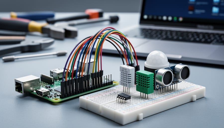
Connect sensors directly to your Raspberry Pi’s GPIO pins to gain precise control, eliminate USB adapter clutter, and troubleshoot connectivity issues that plague plug-and-play alternatives. GPIO (General Purpose Input/Output) integration transforms your Pi from a simple computer into a versatile sensing platform capable of reading temperature, humidity, motion, distance, and dozens of other environmental variables with millisecond precision.
Start by identifying your sensor’s protocol—whether I2C, SPI, or simple digital/analog output—then map the corresponding GPIO pins using a pinout diagram to avoid misconnections that can damage both sensor and Pi. Enable the appropriate interface through raspi-config, install necessary Python libraries like RPi.GPIO or gpiozero, and write initialization code that properly configures pin modes and pull-up/pull-down resistors.
Master advanced sensor integration techniques by learning to implement proper voltage level shifting for 5V sensors, add debouncing for switches and buttons, and create interrupt-driven programs that respond instantly to sensor events rather than polling continuously.
GPIO sensors fail most often due to loose connections, incorrect voltage levels, or software configuration errors. By understanding the fundamental principles of GPIO communication and following systematic troubleshooting steps, you’ll build reliable sensor networks that collect accurate data for home automation, weather stations, robotics projects, and scientific experiments. This guide walks you through everything from basic safety precautions to advanced multi-sensor setups, ensuring your GPIO projects succeed on the first attempt.
What Makes GPIO Sensors Different from Other Raspberry Pi Sensors
GPIO sensors stand apart from their USB and I2C counterparts by connecting directly to your Raspberry Pi’s General Purpose Input/Output pins, giving you unprecedented control over sensor connectivity and functionality. But what exactly makes this difference so significant for your projects?
Think of GPIO pins as the raw building blocks of hardware communication. Unlike USB sensors that come pre-packaged with their own controllers and drivers, GPIO sensors interface directly with your Pi’s processor through individual pins you can configure as inputs or outputs. This direct connection means you’re not limited by predefined protocols or communication standards. You decide exactly how data flows, when it’s read, and how quickly your system responds.
The flexibility advantage becomes clear when you compare approaches. USB sensors are plug-and-play convenient but offer limited customization. I2C sensors use a clever two-wire communication system that’s great for chaining multiple devices, but they introduce protocol overhead and potential addressing conflicts. GPIO sensors, however, give you granular control over timing, voltage levels, and data handling. Need microsecond-precise readings? GPIO delivers. Want to trigger multiple actions simultaneously? You’re in command.
This control extends to power management too. GPIO pins can supply power directly to low-consumption sensors, eliminating extra wiring and power adapters. You can even programmatically switch sensors on and off to conserve energy, something USB sensors can’t easily accomplish.
For advanced integration projects, GPIO pins become essential. Building custom sensor arrays, implementing real-time monitoring systems, or creating precise automation requires the timing accuracy and direct hardware access that only GPIO provides. While USB and I2C have their place for certain applications, GPIO sensors unlock possibilities that simply aren’t available through other interfaces. When you need maximum flexibility and aren’t afraid to dive deeper into hardware programming, GPIO is your gateway to truly custom solutions.
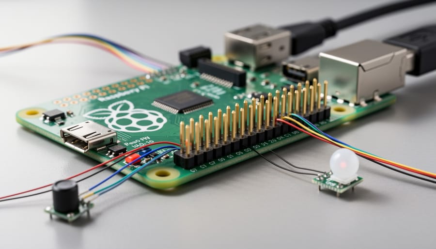
Understanding the Raspberry Pi GPIO Pin Layout
Pin Numbering Systems: BCM vs Board Mode
One of the most common pitfalls when working with GPIO sensors is mixing up the two pin numbering systems available in Raspberry Pi programming. Understanding these systems is essential to avoid the frustrating scenario where your sensor simply won’t respond.
The BOARD numbering system refers to the physical pin numbers on the GPIO header, counting from 1 to 40 based on their position. Pin 1 is always in the corner nearest the SD card slot. This system is straightforward and intuitive for beginners since you can simply count the pins on your physical board.
BCM (Broadcom SOC channel) numbering, on the other hand, uses the GPIO numbers assigned by the Raspberry Pi’s processor chip. These numbers don’t follow the physical layout and can seem random at first glance. For example, physical pin 12 is GPIO18 in BCM mode.
So when should you use each system? BCM is preferred in most advanced projects and online tutorials because it remains consistent across different Raspberry Pi models, even when the physical layout changes. It’s also the default in many modern libraries. However, BOARD mode can be easier for quick prototyping when you’re working directly with a physical diagram.
The critical rule: choose one system and stick with it throughout your entire project. In your Python code, declare your choice at the start using GPIO.setmode(GPIO.BCM) or GPIO.setmode(GPIO.BOARD). Mixing systems mid-project is the leading cause of sensors appearing “dead” when they’re actually connected to the wrong pin entirely.
Voltage Levels and Safety Considerations
One of the most critical safety considerations when working with GPIO sensors is understanding voltage compatibility. The Raspberry Pi operates on 3.3V logic levels, while many sensors and Arduino components use 5V logic. Connecting a 5V sensor output directly to a Raspberry Pi GPIO pin can permanently damage your board, so it’s essential to verify sensor specifications before making connections.
Before purchasing any sensor, check whether it’s designed for 3.3V or 5V operation. Many modern sensors are 3.3V compatible or include built-in level shifting, making them safe to use directly with your Pi. However, if you need to use a 5V sensor, you’ll need a level shifter or voltage divider to protect your GPIO pins. A simple voltage divider using two resistors can step down 5V signals to safe 3.3V levels, though bidirectional level shifter modules are more reliable for complex communication protocols like I2C.
Power supply is equally important. While GPIO pins can provide both 3.3V and 5V power outputs, they have limited current capacity. Drawing too much current can cause instability or damage. For power-hungry sensors, consider using an external power supply with a common ground connection to your Pi. Always double-check your wiring before powering up, and never hot-plug sensors while your Raspberry Pi is running to avoid voltage spikes.
Essential GPIO Sensors Every Raspberry Pi Project Needs
Digital Sensors: Motion, Touch, and Switches
Digital sensors offer some of the most versatile and practical GPIO applications for Raspberry Pi projects. PIR motion sensors detect infrared radiation changes when people or animals move nearby, making them perfect for security systems, automatic lighting, and energy-saving applications. These sensors typically require just three connections: power, ground, and a single GPIO pin for the digital output signal.
Magnetic reed switches provide simple yet effective proximity detection. When a magnet approaches, internal contacts close or open, sending a HIGH or LOW signal to your GPIO pin. They’re commonly used in door and window security monitors, as well as position sensing in robotics projects.
Touch sensors use capacitive technology to detect human contact without mechanical buttons. They offer a modern, wear-resistant alternative to traditional switches and work beautifully for interactive displays or control panels. Standard tactile buttons and switches remain popular for user input, offering reliable, debounced signals when properly configured with pull-up or pull-down resistors.
All these sensors share a common advantage: they provide clean digital signals that are straightforward to read with simple GPIO input commands, making them ideal starting points for beginners transitioning from basic projects to more complex automation systems.
Temperature and Humidity Sensors (DHT11/DHT22)
The DHT11 and DHT22 are go-to environmental sensors for Raspberry Pi projects, measuring both temperature and humidity through a single GPIO pin. These affordable sensors connect easily to your Pi and require just three wires: power, ground, and data.
The DHT11 works well for basic projects, offering temperature readings accurate to plus or minus 2 degrees Celsius and humidity within 5% accuracy. It’s perfect for simple weather stations or room monitoring setups. The DHT22, while slightly more expensive, provides significantly better precision with plus or minus 0.5 degrees Celsius for temperature and 2-5% for humidity. It also handles a wider range of conditions, making it ideal for greenhouse monitoring or outdoor applications.
Both sensors communicate using a one-wire protocol, though you’ll need to install specialized Python libraries like Adafruit_DHT to read the data. A common beginner mistake is forgetting the 10K pull-up resistor on the data line, which can cause unreliable readings.
Popular projects include smart thermostats, bathroom ventilation controllers that activate based on humidity levels, and plant care systems that alert you when conditions drift outside ideal ranges. The DHT22’s superior accuracy makes it better suited for applications where precise environmental control matters.
Analog Sensors with ADC Converters
The Raspberry Pi’s GPIO pins work exclusively with digital signals, but many fascinating sensors operate in the analog world. Light sensors, soil moisture probes, temperature sensors like the TMP36, and potentiometers all output variable voltages that your Pi can’t read directly. This is where Analog-to-Digital Converters (ADCs) become essential.
The MCP3008 is the most popular ADC for Raspberry Pi projects. This affordable chip connects to your Pi via the SPI interface and provides eight analog input channels with 10-bit resolution, meaning it can distinguish 1,024 different voltage levels between 0 and 3.3V. That’s precise enough for most hobbyist applications.
Setting up the MCP3008 requires enabling SPI through raspi-config and installing supporting libraries. The chip uses four GPIO pins: MOSI, MISO, SCLK, and CE0. Once connected, reading analog values becomes straightforward with Python libraries like Adafruit_MCP3008 or gpiozero’s MCP3008 class.
For example, connecting a photoresistor to channel 0 lets you measure light levels. Create a voltage divider circuit with the photoresistor and a 10kΩ resistor, connect the middle point to the MCP3008, and you’re ready to build automatic lighting systems or daylight sensors.
If you need more channels or higher resolution, alternatives like the ADS1115 offer 16-bit precision with four channels via I2C. The trade-off is slower sampling rates compared to the MCP3008’s SPI interface, so choose based on your project’s needs for accuracy versus speed.
Setting Up Your Raspberry Pi for GPIO Sensor Integration
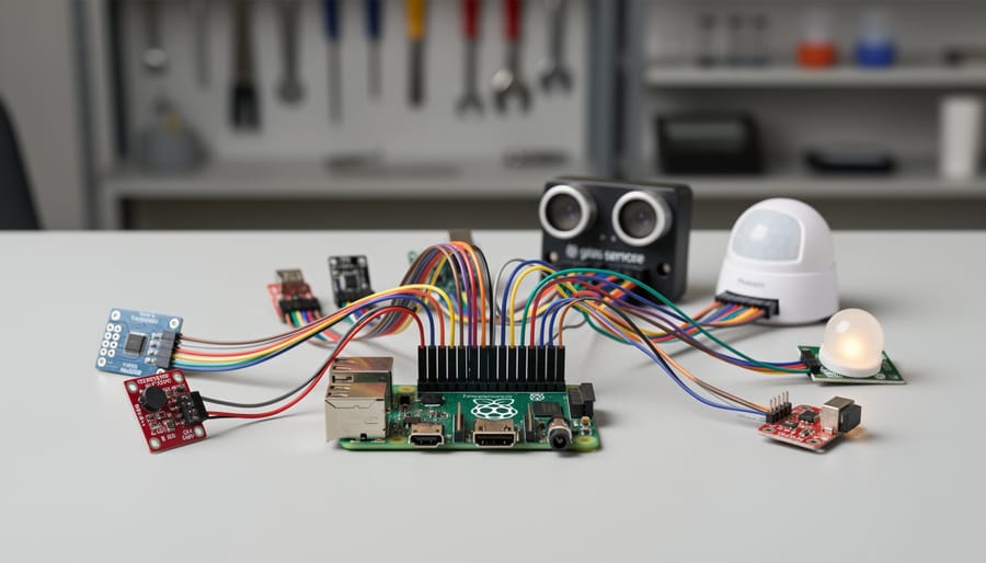
Installing GPIO Libraries: RPi.GPIO vs gpiozero
When it comes to controlling GPIO sensors on your Raspberry Pi, you’ll need to choose between two excellent Python libraries: RPi.GPIO and gpiozero. Understanding their differences will help you select the right tool for your project.
RPi.GPIO is the original GPIO library that’s been around since the early days of Raspberry Pi. It provides low-level control over GPIO pins, giving you precise access to pin states, PWM signals, and interrupt detection. This library is perfect for advanced users who need fine-grained control or are working on timing-critical applications. However, its syntax can feel verbose, and beginners might find the learning curve steep.
gpiozero takes a different approach by offering a high-level, object-oriented interface that’s incredibly beginner-friendly. Instead of managing pin numbers and states manually, you work with intuitive device objects like LED, Button, or MotionSensor. The code is remarkably readable and requires fewer lines to accomplish the same tasks. For example, blinking an LED takes just three lines with gpiozero compared to eight or more with RPi.GPIO.
For beginners and educators, gpiozero is the clear winner. Its simplified syntax lets you focus on understanding sensor behavior rather than wrestling with code complexity. The built-in device classes cover most common sensors, and the documentation includes excellent examples.
Advanced users working on projects requiring precise timing control, custom protocols, or legacy code maintenance might prefer RPi.GPIO’s granular control. The good news? Both libraries can coexist on your system, so you can experiment with each and decide which fits your workflow best.
Wiring Best Practices and Common Mistakes
Getting your GPIO sensor wiring right from the start saves hours of frustration later. Let’s cover the essential practices that keep your projects running smoothly.
Start with a quality breadboard and organize your jumper wires by color. A simple color-coding system works wonders: red for power (3.3V or 5V), black for ground, and other colors for data lines. This visual organization makes troubleshooting significantly easier when things go wrong.
Before powering up your Raspberry Pi, double-check every connection. The most common mistake is accidentally connecting a 5V power line directly to a GPIO pin rated for 3.3V, which can permanently damage your board. Always verify your sensor’s voltage requirements and use level shifters when necessary for 5V sensors.
Keep jumper wires as short as practical to reduce electromagnetic interference and signal degradation. Long, tangled wires aren’t just messy—they can introduce noise into sensitive sensor readings. Secure loose connections firmly, as intermittent contact causes unpredictable behavior that’s difficult to diagnose.
Watch for short circuits by ensuring bare wire ends don’t touch adjacent connections on your breadboard. A magnifying glass helps inspect tight spaces where accidental bridges might form between rows.
When troubleshooting connection issues, work systematically. Test continuity with a multimeter, verify ground connections first, then power, and finally signal lines. Most sensor failures trace back to loose connections or incorrect pin assignments rather than faulty components. Document your working configurations—take photos or create wiring diagrams—so you can replicate successful setups in future projects.
Hands-On Project: Building a Multi-Sensor GPIO System
Required Components and Circuit Diagram
For this project, you’ll need a Raspberry Pi (any model with GPIO pins will work, though the Pi 4 offers the best performance), a DHT22 temperature and humidity sensor (available for $5-10 on Amazon or Adafruit), three female-to-female jumper wires, a 10kΩ pull-up resistor, and a breadboard for easier connections.
When purchasing your DHT22 sensor, look for modules with built-in pull-up resistors to simplify your setup. Budget-friendly alternatives include the DHT11, though it’s less accurate. For jumper wires, invest in quality brands like Elegoo or Dupont to avoid connectivity issues that plague cheap alternatives.
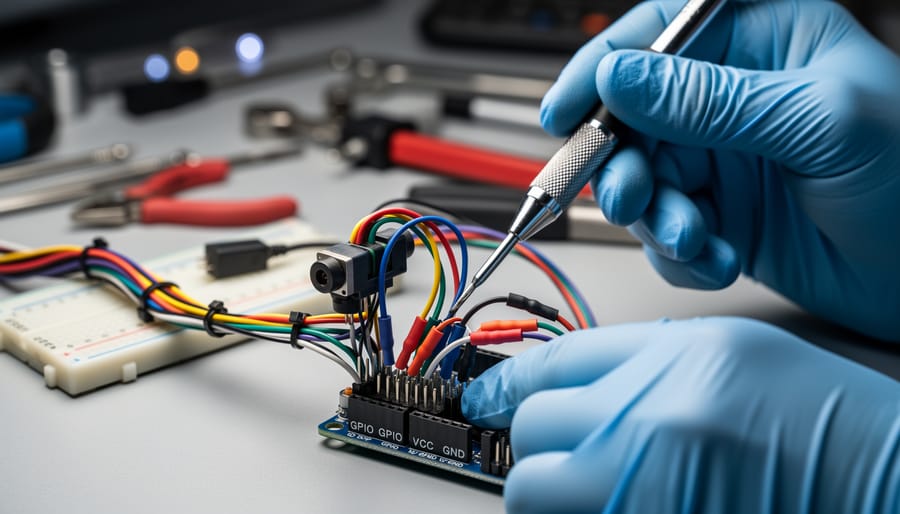
The circuit diagram is straightforward: connect the DHT22’s VCC pin to the Raspberry Pi’s 3.3V power (physical pin 1), the GND pin to any ground pin (physical pin 6 works well), and the DATA pin to GPIO4 (physical pin 7). If your sensor lacks a built-in resistor, place the 10kΩ resistor between the VCC and DATA pins on your breadboard.
Double-check all connections before powering on your Pi. Reversed power connections can damage both your sensor and GPIO pins, so take your time with this step and refer to a GPIO pinout diagram for confirmation.
Writing the Python Code
Now let’s dive into the exciting part: writing the Python code to bring your sensors to life! Don’t worry if you’re relatively new to programming—we’ll walk through each step together.
Start by importing the necessary libraries. You’ll need RPi.GPIO for controlling the pins and time for managing delays between readings:
import RPi.GPIO
import time
Next, configure your GPIO mode. We recommend using BCM numbering, which refers to the GPIO numbers rather than physical pin positions:
RPi.GPIO.setmode(RPi.GPIO.BCM)
For a basic temperature sensor on GPIO pin 4, set it as an input:
sensor_pin = 4
RPi.GPIO.setup(sensor_pin, RPi.GPIO.IN)
Now create a function to read sensor data. This simple example checks the pin state:
def read_sensor(pin):
return RPi.GPIO.input(pin)
For continuous monitoring, wrap your reading logic in a loop:
try:
while True:
sensor_value = read_sensor(sensor_pin)
print(f”Sensor reading: {sensor_value}”)
time.sleep(1)
except KeyboardInterrupt:
RPi.GPIO.cleanup()
The try-except block ensures proper cleanup when you stop the program, preventing GPIO warnings on subsequent runs.
Reading multiple sensors simultaneously is straightforward. Define multiple pins and create a dictionary to store readings:
sensors = {‘temperature’: 4, ‘motion’: 17, ‘light’: 27}
for name, pin in sensors.items():
RPi.GPIO.setup(pin, RPi.GPIO.IN)
Then modify your loop to read all sensors:
for name, pin in sensors.items():
value = RPi.GPIO.input(pin)
print(f”{name}: {value}”)
For more complex sensors requiring specific protocols like I2C or SPI, you’ll use specialized libraries, but the basic structure remains the same. Always remember to call RPi.GPIO.cleanup() when finished to reset your GPIO pins properly.
Testing and Troubleshooting Your Setup
Once you’ve connected your GPIO sensors, it’s time to verify everything works properly. Start with a simple test script that reads sensor data and prints values to the terminal. For digital sensors like motion detectors, check if the pin state changes from LOW to HIGH when triggered. For analog sensors using an ADC, confirm you’re receiving consistent numerical readings within the expected range.
Common issues often stem from loose connections or incorrect pin numbering. Remember that Raspberry Pi supports two numbering schemes: BCM (Broadcom chip-specific) and BOARD (physical pin position). Ensure your code matches your wiring reference. If readings seem unstable, try adding a small delay between sensor polls or implement a pull-up/pull-down resistor to stabilize the signal.
For temperature and humidity sensors, compare readings against known values or calibrated devices. If values drift significantly, check your power supply voltage, as many sensors require stable 3.3V or 5V input. Environmental interference can affect sensitive sensors, so keep wiring short and away from electromagnetic sources.
Use the command line tool ‘gpio readall’ to check pin states in real-time, helping identify whether hardware or software is causing problems. Add error handling to your code that catches failed sensor reads and implements retry logic, making your projects more robust and reliable in real-world applications.
Advanced GPIO Sensor Techniques
Interrupt-Driven Sensor Reading
Polling sensors continuously can drain your Raspberry Pi’s CPU resources and create unnecessary overhead. A smarter approach involves using GPIO interrupts, which allow your Pi to respond instantly when a sensor changes state, while keeping the CPU free for other tasks.
Think of interrupts like a doorbell. Instead of repeatedly checking if someone’s at the door (polling), you wait for the bell to ring (interrupt), then respond. This approach dramatically improves performance and reduces power consumption.
Here’s how to implement interrupt-driven sensor reading. Using the RPi.GPIO library, you can detect rising edges (low to high), falling edges (high to low), or both:
“`python
import RPi.GPIO as GPIO
SENSOR_PIN = 17
def sensor_callback(channel):
print(f”Motion detected on GPIO {channel}!”)
# Your sensor handling code here
GPIO.setmode(GPIO.BCM)
GPIO.setup(SENSOR_PIN, GPIO.IN, pull_up_down=GPIO.PUD_DOWN)
# Add event detection
GPIO.add_event_detect(SENSOR_PIN, GPIO.RISING,
callback=sensor_callback,
bouncetime=300)
# Your main program continues running
try:
while True:
# CPU is free for other tasks
pass
except KeyboardInterrupt:
GPIO.cleanup()
“`
The bouncetime parameter prevents false triggers from mechanical switch bounce. For motion sensors or buttons, 200-300 milliseconds works well.
This technique is particularly valuable when monitoring multiple sensors simultaneously. Instead of checking each sensor in a loop, your Pi responds only when events occur, making your projects more responsive and efficient.
Combining GPIO with I2C and SPI Sensors
Modern sensor projects often benefit from combining different communication protocols to leverage the strengths of each. While basic GPIO sensors excel at simple digital and analog readings, integrating I2C and SPI devices creates powerful hybrid systems capable of sophisticated data collection.
Consider a weather station project: you might use GPIO pins for a simple rain detector and anemometer pulse counting, while simultaneously reading temperature and humidity from an I2C sensor and atmospheric pressure from an SPI device. This combination provides comprehensive environmental monitoring from a single Raspberry Pi.
The key advantage lies in resource management. GPIO sensors typically require dedicated pins for each device, which can quickly exhaust your available connections. I2C devices, however, share just two pins (SDA and SCL) regardless of how many sensors you connect, freeing up GPIO pins for tasks that truly need them. SPI offers faster data transfer speeds, making it ideal for high-frequency sensors alongside slower GPIO inputs.
Implementation is straightforward. First, enable I2C and SPI through raspi-config, then install the necessary Python libraries like smbus2 for I2C and spidev for SPI. Your code can then poll all sensors within a single script, synchronizing data collection and reducing complexity.
For those working on IoT integration projects, this multi-protocol approach ensures you capture every data point needed without overwhelming your GPIO resources. The result is more reliable, scalable sensor networks that grow with your project ambitions.
Common GPIO Sensor Problems and Solutions
Even experienced makers run into GPIO sensor hiccups from time to time. Let’s tackle the most common issues you might face and get your project back on track.
Incorrect or Erratic Readings
If your sensor is spitting out nonsensical data, start by checking your power supply. Many sensors require a stable 3.3V or 5V connection, and voltage drops can cause unreliable readings. Use a multimeter to verify your power rail is delivering the correct voltage under load. Next, examine your pull-up or pull-down resistors. Digital sensors often need these to maintain a defined state when no signal is present. For I2C sensors, 4.7kΩ pull-up resistors on both SDA and SCL lines typically solve communication problems.
No Response from Sensor
When your sensor shows zero activity, first verify your physical connections. A loose jumper wire is the culprit more often than you’d think. Run through each connection systematically, ensuring GPIO pins match your code configuration. Check that you’ve enabled the necessary interfaces in raspi-config, particularly I2C, SPI, or 1-Wire depending on your sensor type. Use diagnostic commands like i2cdetect -y 1 to confirm your Raspberry Pi can see I2C devices on the bus.
GPIO Pin Conflicts
If your sensor worked yesterday but fails today after adding new components, you likely have a pin conflict. Different sensors can’t share the same GPIO pin for different purposes. Review your pin assignments carefully and consult a GPIO pinout diagram. Remember that some pins have special functions you can’t override.
Voltage Level Mismatches
Connecting a 5V sensor output directly to a 3.3V GPIO input can damage your Raspberry Pi. Always use a level shifter or voltage divider when interfacing between different voltage levels. Conversely, some 5V sensors won’t register 3.3V signals from the Pi as valid HIGH states, requiring proper logic level conversion in both directions.
You’ve now gained a solid foundation in working with GPIO sensors on your Raspberry Pi, from understanding the basics of pin layouts to implementing safety measures and troubleshooting common issues. The beauty of GPIO integration lies in its flexibility and reliability—once you master the fundamentals, you can expand your projects in countless directions.
Start small and build confidence with simple sensors like temperature monitors or motion detectors before advancing to more complex multi-sensor arrays. Each project you complete adds to your skills and prepares you for the next challenge. Remember that even experienced makers encounter issues, so don’t get discouraged by setbacks. The troubleshooting techniques covered here will serve you well as you tackle increasingly sophisticated sensor projects.
For continued learning, explore the official Raspberry Pi documentation, which offers detailed GPIO specifications and examples. Online communities like the Raspberry Pi forums and GitHub repositories provide valuable code samples and project inspiration. Consider investing in a GPIO reference card to keep pin configurations handy while working.
The possibilities with GPIO sensors are virtually limitless—from home automation systems to environmental monitoring stations and robotics. Your next breakthrough project is just one sensor connection away. Take what you’ve learned here, apply it to a project that excites you, and watch as your Raspberry Pi transforms into a powerful, sensor-enabled platform ready to tackle real-world challenges.