
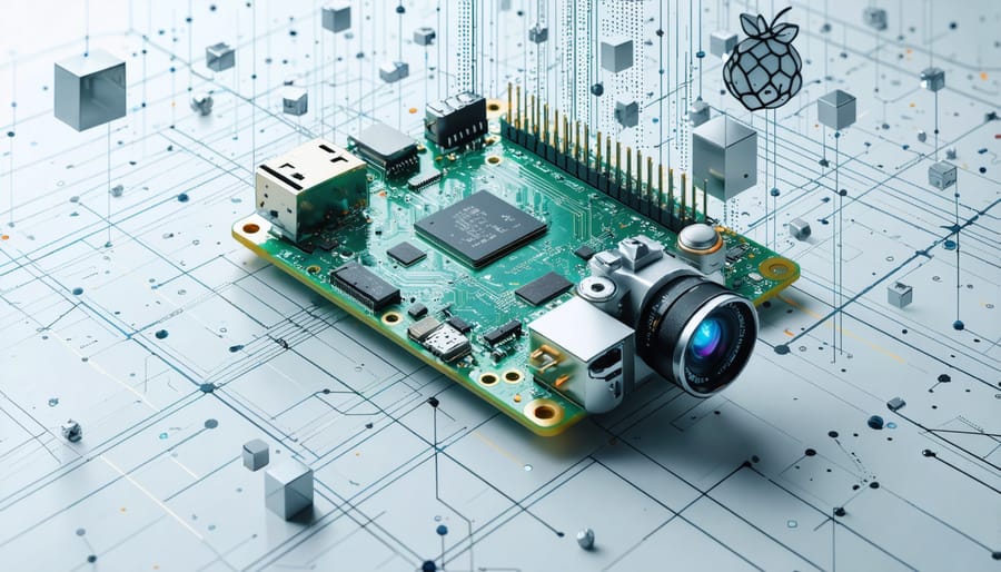
Transform physical objects into detailed 3D models using advanced scanning technology and reverse engineering techniques. This revolutionary process captures complex geometries, surface textures, and dimensional data with sub-millimeter accuracy, enabling makers and engineers to recreate, modify, or improve existing products. Modern 3D scanning combines affordable hardware like structured light sensors or photogrammetry rigs with powerful mesh processing software, democratizing what was once exclusively industrial technology. Whether you’re prototyping new products, preserving historical artifacts, or creating replacement parts, 3D scanning reverse engineering opens up endless possibilities for digital manufacturing and design iteration.
The real power lies in its accessibility – using just a smartphone camera and free software, hobbyists can now capture basic 3D scans. For professional-grade results, structured light scanners built with Raspberry Pi cameras and projectors offer accuracy rivaling commercial systems at a fraction of the cost. This introduction to 3D scanning reverse engineering will guide you through selecting the right hardware, capturing clean scan data, and processing it into usable 3D models ready for manufacturing or modification.
Essential Hardware for 3D Scanning with Raspberry Pi
Camera Options and Setup
For successful 3D scanning, camera selection and setup are crucial elements. Most modern DSLR or mirrorless cameras with manual control settings work well, but the ideal choice is a camera offering at least 20MP resolution and good low-light performance. Popular options include the Canon EOS series or Sony Alpha cameras, though even high-quality smartphone cameras can work for basic scans.
Position your camera on a stable tripod approximately 3-4 feet from the object, ensuring consistent lighting across all angles. For best results, use two or three cameras arranged at 120-degree intervals around the subject. Each camera should be set to manual mode with consistent settings: an aperture of f/8 to f/11 for good depth of field, ISO 100-400 to minimize noise, and a shutter speed appropriate for your lighting conditions.
Proper lighting is essential – use diffused LED panels or soft boxes to create even illumination without harsh shadows. Consider using a turntable for the subject rather than moving the cameras, as this maintains consistent camera positions and lighting throughout the scanning process. Remember to calibrate your cameras using a checkerboard pattern before starting your scan sequence.
Additional Hardware Requirements
A successful 3D scanning setup requires more than just cameras and software. A motorized turntable is essential for capturing consistent, automated 360-degree scans of objects. Look for turntables with adjustable rotation speeds and the ability to handle your expected object weights. Most hobbyist setups work well with turntables that can support 2-5 kg.
Proper lighting is crucial for accurate scans. Use at least two diffused LED light sources to eliminate harsh shadows and ensure even illumination. Adjustable LED panels or ring lights work well, allowing you to modify lighting angles and intensity based on your subject’s size and surface properties.
For smaller objects, consider adding a lightbox or photo tent to control ambient lighting and create a neutral background. A set of calibration targets or patterns helps ensure accurate scaling and alignment during post-processing.
Additional useful tools include a sturdy tripod with adjustable height, anti-vibration pads for the turntable, and a selection of backdrop materials in neutral colors (preferably matte black or white) to enhance contrast and reduce unwanted reflections.
Software Solutions for 3D Scanning

Open-Source Options
For those working with limited budgets, several powerful open-source options make 3D scanning accessible without breaking the bank. MeshRoom stands out as a popular photogrammetry solution that transforms regular photos into detailed 3D models. It’s particularly effective when combined with Raspberry Pi software solutions for automated capture setups.
OpenScan offers both hardware designs and software tools, making it an excellent choice for DIY enthusiasts. The software processes images from multiple angles to create accurate 3D models, and the community actively shares improvements and modifications.
FreeCAD’s Reverse Engineering Workbench provides tools for converting point clouds into solid models, while CloudCompare offers robust point cloud processing capabilities. Both applications work well with data from various scanning methods and export formats compatible with most 3D printing software.
For basic scanning needs, DAVID-LaserScanner provides a straightforward solution that works with ordinary webcams. While it may not match commercial solutions’ precision, it’s perfect for learning the fundamentals of 3D scanning.
These open-source tools often receive regular updates from their communities, ensuring continued improvement and compatibility with modern hardware. Their documentation and active forums make them particularly suitable for beginners looking to explore 3D scanning without significant investment.
Premium Software Alternatives
For professional-grade 3D scanning and reverse engineering, several premium software solutions offer advanced features that significantly enhance accuracy and workflow efficiency. Artec Studio Professional stands out with its powerful algorithms for high-resolution mesh processing and automated alignment tools. This software excels at handling complex geometries and provides comprehensive quality control features.
Geomagic Design X, now part of 3D Systems, is widely considered the industry standard for reverse engineering. It seamlessly integrates with various 3D modeling software and offers sophisticated tools for converting scan data into feature-based CAD models. Its automated feature recognition capabilities significantly reduce processing time.
Another notable option is Rapidform XOR, which specializes in creating parametric solid models from scan data. It offers excellent deviation analysis tools and automatic surface optimization features that help maintain design intent during the reverse engineering process.
VXmodel, while less expensive than some competitors, provides a comprehensive toolset for mesh editing, surface extraction, and CAD model creation. It’s particularly well-suited for users who need to maintain accuracy while working with complex organic shapes.
These premium solutions, while requiring significant investment, offer superior accuracy, automation features, and professional-grade output that justify their cost for serious projects and commercial applications.
Setting Up Your Scanning Environment
A successful 3D scanning setup requires careful attention to environmental conditions and equipment positioning. Start by choosing a well-lit room with consistent, diffused lighting. Avoid direct sunlight or harsh spotlights, as these can create unwanted shadows and reflections that interfere with scan quality. If possible, use LED panels or ring lights positioned at 45-degree angles to provide even illumination across your subject.
The scanning surface should be stable and non-reflective. A matte-finished turntable can be invaluable for capturing all angles of your object, while ensuring consistent rotation speed. Place your subject on a neutral-colored background – medium gray works best as it provides good contrast without causing exposure issues.
Position your scanning device (whether it’s a structured light scanner, laser scanner, or photogrammetry setup) at the optimal distance recommended by your hardware manufacturer. For most desktop scanning applications, this is typically between 30-60 centimeters from the subject. Consider mounting your scanner on a stable tripod or custom mounting solution to minimize vibration and maintain consistent results.
Temperature and humidity control are often overlooked but crucial factors. Keep your scanning environment at a stable room temperature (around 20-22°C) to prevent thermal expansion or contraction of materials. Humidity should be moderate (40-60%) to avoid static electricity issues that can affect electronic components.
For smaller objects, consider creating a light tent or booth to control lighting conditions perfectly. This can be as simple as a DIY solution using white translucent fabric or as sophisticated as a professional light box. Keep the scanning area clean and dust-free, as particles can create noise in your scans.
Remember to calibrate your scanning equipment before each session using the manufacturer’s recommended calibration tools and procedures. This ensures accuracy and repeatability in your scanning results. Taking these environmental considerations into account will significantly improve the quality of your 3D scans and make the reverse engineering process more efficient.
Step-by-Step Scanning Process
The 3D scanning process follows a systematic workflow that ensures accurate and reliable results. Begin by preparing your scanning environment with proper lighting – diffused, even illumination works best to prevent harsh shadows. Position your object on a non-reflective, matte surface, ideally on a turntable for easier 360-degree capture.
Start with a calibration scan using a known reference object to ensure your scanner’s accuracy. Most scanning software will guide you through this process, which typically takes 5-10 minutes. Once calibrated, position your object at the optimal scanning distance – usually between 30-60cm depending on your scanner’s specifications.
Commence scanning by taking multiple overlapping passes around your object. Aim for at least 30% overlap between each scan to ensure proper alignment during processing. For complex geometries, you’ll need to capture from various angles, including top-down views to catch all surfaces. Pay special attention to deep recesses and overhanging features, as these areas often require additional scans.
After capturing the raw scan data, begin the post-processing phase. First, align your individual scans using your software’s registration tools. Most modern scanning software offers both automatic and manual alignment options. Clean up any noise or artifacts in your point cloud data, removing any spurious points or scanning artifacts that don’t belong to your object.
Next, merge your aligned scans into a single mesh. This process, often called fusion or meshing, creates a continuous surface from your point cloud data. Apply hole-filling algorithms to address any small gaps in your mesh, but be cautious with large holes as these might require additional scanning.
Finally, optimize your mesh for reverse engineering by reducing polygon count while maintaining critical features. Export your processed scan in a format compatible with your CAD software – common choices include STL, OBJ, or STEP files for parametric modeling.
Remember to document your scanning parameters and processing steps. This documentation proves invaluable when troubleshooting or repeating the process for similar objects. For best results, consider creating a scanning checklist that you can refine based on your experience with different object types and materials.
Post-Processing and Model Refinement
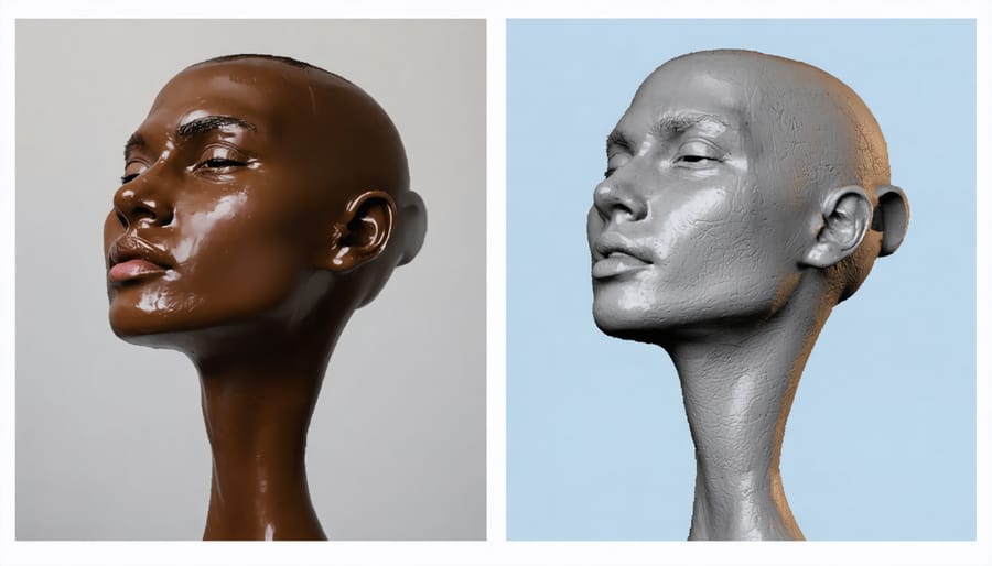
After capturing your 3D scan data, the real magic happens during post-processing and model refinement. This crucial stage transforms raw scan data into usable 3D models through several key steps. Start by cleaning up point cloud data to remove noise and artifacts – these are usually scattered points that don’t belong to your actual object. Many scanning software packages include automated cleanup tools, but manual inspection is often necessary for best results.
Next, focus on mesh optimization. This involves filling holes, smoothing rough surfaces, and ensuring your model is watertight (completely sealed). Popular tools like Meshlab or Blender offer powerful post-processing techniques that can dramatically improve model quality. Pay special attention to areas with complex geometry or sharp edges, as these typically require more refinement.
For reverse engineering purposes, consider converting your mesh into a CAD-friendly format. This might involve creating primitive shapes from your scan data or using specialized software to generate parametric models. Tools like FreeCAD or Fusion 360 can help transform organic shapes into precise, measurable geometries.
Don’t forget to optimize your model’s polygon count. While high-resolution scans provide excellent detail, they can be unwieldy to work with. Decimation tools can reduce polygon count while maintaining essential features, making your models more manageable for subsequent modifications or 3D printing.
Finally, validate your processed model against the original object or reference measurements. This ensures accuracy and helps identify areas that might need additional refinement before moving forward with your reverse engineering project.
3D scanning for reverse engineering has revolutionized how we approach product development and design replication. By following the techniques and workflows discussed, you can now confidently embark on your own scanning projects with accessible tools and methodologies. Remember that success comes through practice and experimentation – start with simple objects and gradually work your way up to more complex geometries. Whether you’re preserving historical artifacts, creating replacement parts, or launching into exciting new 3D modeling projects, the skills you’ve learned here provide a solid foundation. Keep exploring different scanning methods, refining your post-processing techniques, and sharing your experiences with the maker community. With dedication and the right approach, you’ll soon be turning physical objects into detailed digital models that can be modified, improved, and brought back to life through 3D printing. The possibilities are endless – now it’s time to start scanning and creating!