
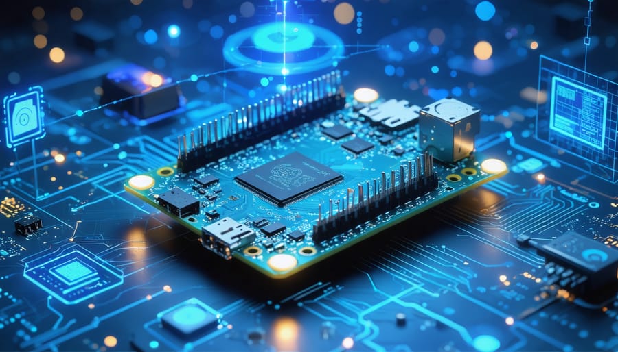
Unlock the full potential of embedded computing with the Raspberry Pi Compute Module 3+ IO Board, a versatile development platform that transforms how we approach industrial automation and custom hardware projects. This specialized carrier board serves as the perfect foundation for prototyping complex embedded systems, offering extensive GPIO access, multiple display outputs, and camera interfaces in a compact, industrial-grade package. Whether you’re developing IoT solutions, creating custom control systems, or building automated manufacturing equipment, the CM3 IO Board provides the essential hardware interfaces and reliability needed for professional-grade applications. Its robust design and comprehensive documentation make it an ideal choice for both rapid prototyping and production-ready deployments, enabling developers to bridge the gap between concept and commercial implementation efficiently.
Understanding the CM3+ IO Board Architecture
Key Hardware Features
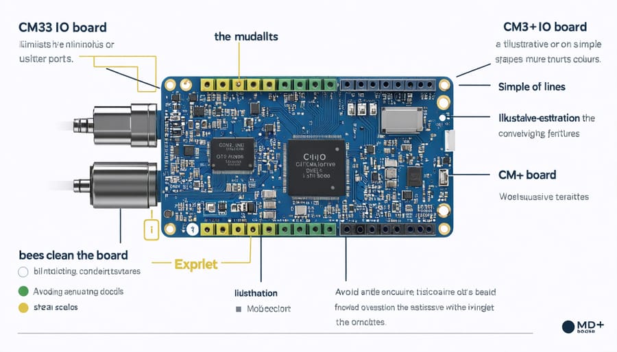
The Raspberry Pi Compute Module 3 IO board serves as a development platform that unlocks the full compute module capabilities through its comprehensive array of interfaces and connectivity options. At its heart, the board features a standard SODIMM connector that securely houses the Compute Module 3 or 3+.
The IO board comes equipped with two full-size HDMI ports supporting HD video output, two USB 2.0 ports for peripheral connectivity, and a MicroUSB port for programming and power delivery. For networking and communication, it includes a Gigabit Ethernet port and 28 GPIO pins that are readily accessible through pin headers.
Storage expansion is facilitated through a microSD card slot, while the board also features CSI and DSI connectors for camera and display interfaces respectively. Power users will appreciate the presence of PCI Express interfaces and the flexible power input options, including a 12V DC jack and USB power delivery.
The board’s layout is thoughtfully designed with clear labeling and ample spacing between components, making it ideal for both prototyping and production environments. Additional features include LED indicators for power and activity status, a real-time clock (RTC) battery backup connector, and multiple test points for debugging and development purposes.
Power and Performance Capabilities
The Compute Module 3 IO board’s power capabilities are designed to support robust development and prototyping needs. Understanding the power requirements for Raspberry Pi modules is crucial for optimal performance. The board accepts power through either USB or a dedicated 12V DC jack, offering flexibility in power source selection.
When powered via USB, the board requires a stable 5V supply capable of delivering at least 2A. The 12V DC input option is particularly useful for industrial applications or scenarios requiring additional power for peripherals. The board features built-in voltage regulators that ensure stable power delivery to the Compute Module and connected components.
Performance-wise, the IO board unleashes the full potential of the CM3, providing access to all GPIO pins and interfaces. The board’s power management system supports the CM3’s maximum processing capabilities, allowing it to run at full speed without thermal throttling under normal conditions.
For resource-intensive applications, the board includes mounting points for additional cooling solutions. The power distribution system is designed to handle multiple USB devices, display outputs, and GPIO accessories simultaneously, making it ideal for complex projects and prototypes.
Remember to monitor power consumption when adding peripherals, as the total draw shouldn’t exceed the power supply’s capabilities. The board includes power protection features to prevent damage from voltage spikes or reverse polarity.
Setting Up Your CM3+ IO Board
Initial Hardware Setup
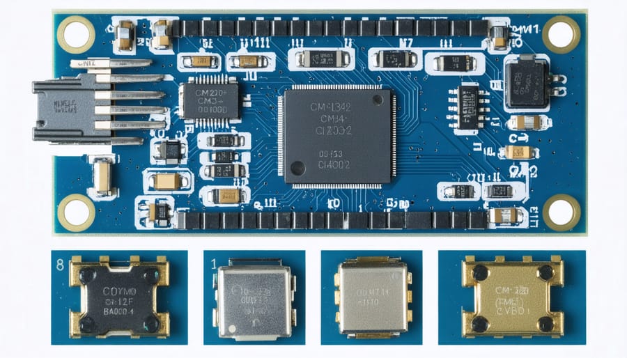
Before powering up your Compute Module 3 IO board, ensure you have a clean, static-free workspace. Start by carefully inserting the Compute Module 3 into the SODIMM connector, keeping it at a 45-degree angle before gently pressing it down until it clicks into place. The module should sit firmly and evenly in the connector.
Connect a 5V power supply rated at least 2A to the micro-USB power input port. For development purposes, you’ll need to connect a USB cable from your computer to the USB slave port (marked “USB SLAVE”) on the IO board. This connection enables you to program the Compute Module’s eMMC storage or boot from USB.
The board features multiple USB ports, an HDMI connector, and GPIO pins. For basic setup, connect a keyboard and mouse to the USB ports and attach a display via the HDMI port. If you’re planning to use network connectivity, you’ll need to connect either a USB Wi-Fi adapter or use the Ethernet port.
Ensure all jumpers are in their default positions as specified in the board’s documentation. Pay special attention to the J4 boot mode jumper – it should be set according to whether you’re booting from eMMC or USB. Double-check all connections before applying power to avoid any potential damage to the board or module.
Software Configuration
Setting up the software for your Compute Module 3 IO board begins with installing the operating system. The most common choice is Raspberry Pi OS (formerly Raspbian), which can be downloaded from the official Raspberry Pi website. Unlike standard Raspberry Pi boards, the CM3 requires a slightly different installation process using the usbboot tool.
First, install the usbboot tool on your host computer. This enables the host to recognize the CM3 when it’s in USB slave mode. Connect your CM3 IO board to your computer via USB, ensuring the J4 jumper (USB SLAVE BOOT ENABLE) is set correctly. With the board powered on, your computer should detect it as a new USB device.
Using rpiboot, flash the Raspberry Pi OS image onto the CM3’s eMMC storage. This process might take a few minutes, depending on your connection speed and the size of the OS image. Once completed, remove the J4 jumper and reboot the board.
For the initial setup, connect a display via HDMI and a keyboard through USB. The first boot will launch the Raspberry Pi configuration wizard, where you can set your locale, timezone, and WiFi credentials if needed. Enable any specific interfaces you plan to use, such as I2C or SPI, through the raspi-config tool.
Remember to update your system regularly using the terminal commands ‘sudo apt update’ and ‘sudo apt upgrade’ to ensure optimal performance and security.
Troubleshooting Common Issues
When working with the Compute Module 3 IO board, you might encounter several common issues. Here’s how to resolve them:
If your board isn’t powering up, first check the J4 power selection jumper. It must be set correctly for either USB or external power supply. Also, verify that your power supply can deliver sufficient current (recommended 2A minimum).
For boot problems, ensure the EMMC_DISABLE_N jumper is set correctly. If using eMMC storage, it should be off; for SD card boot, it should be on. Double-check that your bootloader files are properly installed and not corrupted.
USB connectivity issues often stem from incorrect USB slave configuration. Make sure the USBBOOT utility is properly installed on your host computer and that you’re using a high-quality USB cable capable of data transfer.
Display problems are usually related to incorrect HDMI configuration. Verify your display settings in config.txt and ensure your monitor supports the resolution you’re trying to use.
If experiencing network connectivity issues with add-on cards, check that the PCIe lanes are properly configured in your device tree overlay.
For programming difficulties, confirm that your development environment is properly set up and that you have the latest version of Raspbian installed. Remember to regularly update your system packages using apt-get update and apt-get upgrade commands.
Practical Applications and Projects
Industrial Applications
The Raspberry Pi Compute Module 3 IO board has found significant applications in industrial environments, thanks to its robust design and extensive connectivity options. Many manufacturers use it for automated testing systems, where its numerous GPIO pins enable connection to multiple sensors and testing equipment simultaneously. The board’s ability to handle 24/7 operation makes it ideal for industrial monitoring and control systems.
In factory automation, the IO board serves as a cost-effective solution for managing assembly line processes and quality control operations. Its flexibility allows for custom configurations of industrial sensors, actuators, and communication interfaces, making it suitable for diverse manufacturing scenarios. Companies often integrate it into their existing industrial systems to add modern connectivity and processing capabilities without complete system overhauls.
The board’s support for industrial protocols and interfaces, combined with its compact form factor, makes it perfect for edge computing applications in Industry 4.0 environments. It’s commonly used in data collection and processing stations, where it can gather information from industrial equipment and perform preliminary analysis before sending data to central servers.
Temperature monitoring, vibration analysis, and predictive maintenance systems frequently utilize the IO board’s capabilities. Its reliability and the ability to operate in various environmental conditions have made it a popular choice for industrial IoT applications, where consistent performance is crucial.
DIY Project Ideas
The Raspberry Pi Compute Module 3 IO board opens up countless possibilities for exciting DIY projects. Here are some inspiring project ideas to get you started:
Create a custom home automation controller by utilizing the board’s extensive GPIO pins. You can connect various sensors and relays to control lighting, temperature, and security systems throughout your home. The IO board’s flexible power options make it perfect for permanent installation.
Build a compact industrial control system by taking advantage of the board’s robust design. Connect industrial sensors and actuators to monitor and control manufacturing processes, or develop a sophisticated data logging system for research applications.
For educational purposes, develop a hands-on learning platform that teaches students about embedded systems. The exposed interfaces make it easy to demonstrate concepts like I2C communication, SPI protocols, and GPIO programming. Students can physically trace connections and understand hardware interactions.
Photography enthusiasts can create a high-speed camera trigger system. The board’s multiple USB ports allow connection to cameras, while its GPIO pins can interface with various triggers like sound sensors or laser barriers.
Consider building a custom retro gaming console. The board’s HDMI output and USB ports make it perfect for connecting displays and controllers, while its compact form factor allows for creative case designs.
These projects showcase the versatility of the CM3 IO board while providing valuable learning experiences in hardware development and programming.
Advanced Configurations
To maximize the potential of your CM3 IO board, several advanced configurations can enhance its performance and functionality. Start by adjusting the boot configurations through the dedicated jumpers to enable flexible boot options from either eMMC or USB. For optimal performance, consider implementing active cooling solutions, especially when running processor-intensive applications.
The board’s UART ports can be configured for various baud rates and protocols, making it ideal for IoT applications. Take advantage of the configurable GPIO pins by implementing custom pin mappings through device tree overlays. This flexibility allows for advanced compute module configurations that can support multiple peripherals simultaneously.
Power users should explore the FPC connector’s capabilities for custom display implementations and consider utilizing the JTAG interface for advanced debugging. The PCIe interface can be leveraged for high-speed expansion cards, though this requires careful power management consideration.
For storage optimization, implement wear leveling on the eMMC storage and consider using external USB storage for data-intensive applications. The board’s versatile power supply options can be configured for either 5V or 3.3V operation, depending on your project requirements. Remember to properly configure the boot order in config.txt when implementing multiple storage solutions.
The Raspberry Pi Compute Module 3 IO Board serves as an essential development platform that opens up countless possibilities for both hobbyists and professional developers. Throughout this article, we’ve explored its versatile features, from the extensive GPIO pins to the multiple interface options that make it a powerful tool for custom computing solutions.
Whether you’re building an industrial control system, developing a custom IoT device, or creating an educational platform, the CM3 IO Board provides the flexibility and functionality needed to bring your projects to life. Its compatibility with various operating systems and the robust development environment make it an excellent choice for both beginners and experienced developers.
As you begin your journey with the CM3 IO Board, remember to start with basic configurations before moving on to more complex projects. Take advantage of the growing community resources and documentation available online to support your development process. Consider joining online forums and discussion groups where you can share experiences and learn from other developers working with similar hardware.
Looking ahead, the CM3 IO Board continues to be a relevant platform for embedded systems development, even as newer Compute Module versions emerge. Its established ecosystem and proven reliability make it a solid choice for long-term projects and production deployments.
For your next steps, we recommend starting with simple GPIO projects to familiarize yourself with the board’s capabilities before advancing to more complex applications. Remember to always follow proper safety guidelines and maintain good documentation of your development process.