
# Unlocking Motion Sensing: Your Complete Guide to the ADXL345 and Raspberry Pi
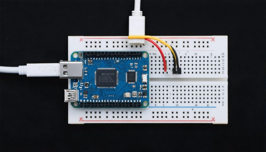
Connect the ADXL345 accelerometer to your Raspberry Pi’s I2C or SPI pins to measure tilt, vibration, and movement in three dimensions. This tiny sensor opens up possibilities for creating earthquake detectors, gesture-controlled projects, activity trackers, and robotics applications—all for under $5.
**Wire the sensor correctly** by connecting VCC to 3.3V, GND to ground, SDA to GPIO 2, and SCL to GPIO 3 on your Raspberry Pi’s GPIO header. Enable I2C communication through the Raspberry Pi configuration tool with a single command, then verify the connection using i2cdetect to confirm your ADXL345 appears at address 0x53.
**Install the necessary Python libraries** including Adafruit-Blinka and adafruit-circuitpython-adxl34x to communicate with your sensor. These pre-built libraries handle the complex register manipulation and data conversion, letting you read acceleration data with just three lines of code.
**Calibrate your measurements** by reading baseline values when the sensor sits flat, then apply simple offsets to account for manufacturing variations. Understanding the sensor’s ±2g to ±16g range settings helps you optimize sensitivity for your specific application—whether detecting subtle vibrations or measuring high-impact forces.
This guide walks you through each step with practical examples, troubleshooting common connection issues, and building three real-world projects. By the end, you’ll transform raw sensor data into meaningful insights for your next creative build.
What Makes the ADXL345 Special for Raspberry Pi Projects
Key Technical Specifications That Matter
The ADXL345 packs impressive capabilities into a tiny package, and understanding its key specifications will help you determine if it’s the right sensor for your project.
**Measurement Range**: The ADXL345 offers selectable measurement ranges of ±2g, ±4g, ±8g, and ±16g (where g equals Earth’s gravity). Think of this as sensitivity settings—±2g works perfectly for detecting device orientation or gentle movements, while ±16g can capture high-impact events like dropping or sudden collisions. Most Raspberry Pi projects use the ±2g or ±4g settings for everyday applications.
**Resolution**: With 10-bit resolution at full range and up to 13-bit in higher sensitivity modes, the ADXL345 detects incredibly subtle movements. This means you can capture approximately 1024 different values across your selected range, making it sensitive enough for precise tilt sensing or gesture recognition projects.
**Power Consumption**: Drawing just 23-40 microamps in measurement mode and as low as 0.1 microamps in standby, this sensor is remarkably efficient. For battery-powered Raspberry Pi projects like weather stations or portable motion detectors, this low power draw extends operating time significantly.
**Communication Protocols**: The ADXL345 supports both I2C and SPI communication, giving you flexibility in how you connect it to your Raspberry Pi. I2C uses just two wires for data transmission and works great for most projects, while SPI offers faster data rates if you’re sampling acceleration at high frequencies. Most beginners start with I2C due to its simplicity and adequate speed for typical applications.
Real-World Applications You Can Build Today
The ADXL345’s versatility opens up exciting possibilities for practical projects you can start building right away. Here are some proven applications that showcase this sensor’s capabilities:
**Motion-Activated Security Systems**: Transform your Raspberry Pi into a smart security device by detecting unexpected movements or vibrations. The ADXL345 can trigger alerts, cameras, or alarms when it senses disturbances, making it perfect for motion-activated systems. This pairs wonderfully with other home automation projects for comprehensive protection.
**Tilt Detection Devices**: Create intelligent positioning monitors for objects that need to stay level. Whether you’re building a self-balancing robot, a package orientation tracker, or a digital spirit level, the ADXL345’s tilt-sensing capabilities provide accurate angle measurements in real-time.
**Vibration Monitoring Systems**: Monitor machinery, appliances, or structures for unusual vibrations that might indicate maintenance needs. This predictive maintenance approach can prevent equipment failures and is particularly valuable in industrial or workshop settings.
**DIY Step Counters and Fitness Trackers**: Build your own wearable fitness device that counts steps, tracks activity levels, and monitors movement patterns. The sensor’s low power consumption makes it ideal for battery-powered wearables.
**Gaming Controllers**: Design custom motion-controlled game interfaces where physical movements translate into gameplay actions. Tilt, shake, and rotate your controller for an immersive gaming experience.
**Earthquake and Seismic Monitors**: Set up a basic seismic detection system to record ground movements and vibrations. While not scientifically precise, it’s an excellent educational tool for understanding seismic activity in your area.
Each project offers hands-on learning opportunities while creating genuinely useful devices for everyday life.
What You’ll Need to Get Started
Before diving into your ADXL345 accelerometer project, let’s gather everything you’ll need. Don’t worry—this is a budget-friendly project that won’t break the bank!
**Hardware Components:**
First up is the **ADXL345 module** itself. Look for breakout boards from reliable manufacturers like Adafruit or SparkFun, which typically cost between $8-15. These come pre-soldered with pull-up resistors and voltage regulators, making them beginner-friendly. The GY-291 module is another popular alternative, often available for around $5-8 on platforms like Amazon or AliExpress.
For your **Raspberry Pi**, any model with GPIO pins will work perfectly—the Raspberry Pi 3 Model B+, Raspberry Pi 4, or even the compact Raspberry Pi Zero W are all excellent choices. If you’re starting fresh, the Raspberry Pi 4 (2GB or 4GB) offers the best balance of performance and value at approximately $35-55.
You’ll also need **female-to-female jumper wires** (a pack of 40 costs around $5) for making connections, and optionally, a **breadboard** ($5-10) if you want to add additional components or create a more organized setup for prototyping.
**Software Requirements:**
On the software side, ensure you’re running **Raspberry Pi OS** (formerly Raspbian), preferably the latest Bullseye version. You’ll need Python 3 pre-installed (which comes standard), along with specific libraries: **smbus** or **smbus2** for I2C communication, and **RPi.GPIO** for pin control. We’ll walk through installing these libraries via pip during the setup process.
**Total estimated cost:** $25-45 if you already own a Raspberry Pi, or $60-100 for a complete starter kit.
Connecting the ADXL345 to Your Raspberry Pi
Understanding the Pin Configuration
The ADXL345 accelerometer features six pins that connect to your Raspberry Pi, and understanding each one is essential for successful integration. Let’s break down what each pin does and how to wire them correctly.
**VCC (Power Supply):** This pin powers the sensor and accepts 3.3V from your Raspberry Pi. While the ADXL345 can handle 2.0V to 3.6V, always use the 3.3V pin on your Pi to ensure stable operation. Never connect it to the 5V pin, as this could damage both your sensor and Raspberry Pi.
**GND (Ground):** Connect this to any ground pin on your Raspberry Pi to complete the electrical circuit. This provides the reference voltage for all measurements.
**SCL (Serial Clock Line):** This pin carries the clock signal for I2C communication. On the Raspberry Pi, connect it to GPIO 3 (physical pin 5), which is the designated I2C clock pin.
**SDA (Serial Data Line):** This handles data transmission between the sensor and your Pi. Wire this to GPIO 2 (physical pin 3), the I2C data pin on your Raspberry Pi.
**SDO (Serial Data Output):** This pin determines the I2C address of your ADXL345. When connected to GND, the address is 0x53; when connected to VCC, it becomes 0x54. For single-sensor setups, connecting to GND is standard practice.
**CS (Chip Select):** Used for SPI communication mode. For I2C projects, connect this pin directly to VCC to disable SPI mode and ensure proper I2C functionality.
Wiring Diagram and Connection Steps
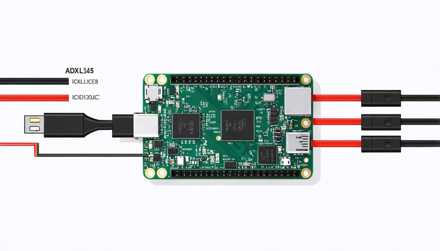
Connecting your ADXL345 accelerometer to the Raspberry Pi requires careful attention to the I²C interface pins. Follow these numbered steps to ensure a reliable connection:
**Step 1:** Power down your Raspberry Pi completely before making any connections to prevent electrical damage.
**Step 2:** Identify the I²C pins on your Raspberry Pi’s GPIO header. You’ll need pins 1 (3.3V), 3 (SDA), 5 (SCL), and 6 (Ground).
**Step 3:** Connect the ADXL345’s VCC pin to the Raspberry Pi’s 3.3V power (Pin 1). Never use 5V as it may damage the sensor.
**Step 4:** Connect the ADXL345’s GND pin to any ground pin on the Pi (Pin 6 works well).
**Step 5:** Connect the sensor’s SDA pin to GPIO 2 (Pin 3) on the Raspberry Pi.
**Step 6:** Connect the sensor’s SCL pin to GPIO 3 (Pin 5) on the Raspberry Pi.
**Step 7:** If your ADXL345 module has CS (Chip Select) and SDO pins, connect CS to 3.3V and leave SDO unconnected for default I²C address configuration.
**Troubleshooting Tips:** Loose connections are the most common issue. Ensure jumper wires are firmly seated in both the GPIO header and sensor pins. If readings seem erratic, try different jumper wires as they can wear out. Double-check that you’re using 3.3V, not 5V. Consider using a breadboard for more stable connections during prototyping phases.
Setting Up Your Raspberry Pi Software Environment
Enabling I2C Communication
Before your Raspberry Pi can communicate with the ADXL345 sensor, you’ll need to enable the I2C interface. This is a straightforward process that takes just a few minutes.
Start by opening the Raspberry Pi configuration tool. In your terminal, type:
“`
sudo raspi-config
“`
Navigate to **Interfacing Options** (or **Interface Options** on newer versions), then select **I2C** and choose **Yes** to enable it. Reboot your Pi to apply the changes.
Once rebooted, verify that I2C is working properly by installing the necessary tools:
“`
sudo apt-get update
sudo apt-get install -y i2c-tools
“`
Now check if your Raspberry Pi detects connected I2C devices:
“`
sudo i2cdetect -y 1
“`
You should see a grid displaying addresses. If no devices are connected yet, the grid will be empty—that’s perfectly normal! Once you connect your ADXL345 sensor, you’ll see its address appear (typically **0x53** or **0x1D** depending on your wiring). This confirms your I2C interface is active and ready for sensor communication.
Installing Required Python Libraries
Before you can start communicating with your ADXL345 sensor, you’ll need to install a few essential Python libraries on your Raspberry Pi. These packages will handle the complex I2C communication protocols, making your coding experience much smoother.
First, ensure your system is up to date by running `sudo apt-get update && sudo apt-get upgrade` in the terminal. Next, install the SMBus library, which enables I2C communication: `sudo apt-get install python3-smbus i2c-tools`. This package is crucial for basic sensor interaction.
For a more user-friendly approach, we recommend installing Adafruit’s CircuitPython library. Simply run `sudo pip3 install adafruit-circuitpython-adxl34x` to get the latest stable version. This library simplifies sensor initialization and data reading with intuitive Python commands.
If you prefer working with Python 2 (though Python 3 is recommended), replace `pip3` with `pip` in the commands above. To verify successful installation, type `python3 -c “import adafruit_adxl34x”` in your terminal—no error message means you’re ready to proceed! These libraries work seamlessly with most Raspberry Pi models and recent Raspbian OS versions.

Writing Your First ADXL345 Python Script
Understanding the Output Data
The ADXL345 measures acceleration along three perpendicular axes—X, Y, and Z—providing a complete picture of movement in three-dimensional space. These readings are typically expressed in “g” units, where 1g equals Earth’s gravitational acceleration (approximately 9.8 m/s²). Understanding these values is key to making sense of your sensor data.
When your ADXL345 sits flat on a table with the chip facing up, you’ll see approximately 0g on the X and Y axes, while the Z axis reads around +1g (or -1g if flipped upside down). This happens because gravity constantly pulls downward, and the sensor detects this force along whichever axis aligns with it.
Let’s explore how different movements affect readings. Tilting your sensor forward makes the X axis register positive or negative values depending on direction, while the Y axis responds to side-to-side tilting. Shaking the device produces rapid fluctuations across all three axes as acceleration changes quickly. If you’re building a step counter, you’ll notice periodic spikes in the vertical axis with each footfall. For gaming controllers, smooth tilting creates gradual value changes perfect for steering inputs.
The raw data from your Python script will display decimal values—for example, `X: 0.03, Y: -0.02, Z: 0.98`. Values near zero indicate little to no acceleration along that axis, while larger numbers show active movement or tilting. Most applications use these readings to calculate orientation, detect motion patterns, or trigger specific actions based on threshold values you define.
Practical Project: Building a Motion-Activated Alert System
Let’s build a practical motion-activated alert system that triggers an LED and sends a notification when it detects significant movement. This project is perfect for creating a simple security monitor or package delivery detector.
**What You’ll Need**
Beyond your Raspberry Pi and ADXL345 sensor (already connected via I2C), gather an LED, a 220-ohm resistor, and a few jumper wires. Connect the LED’s positive leg to GPIO pin 17 and the negative leg through the resistor to ground.
**The Core Concept**
Our system continuously monitors acceleration values and triggers an alert when movement exceeds a defined threshold. The ADXL345 measures acceleration along three axes (X, Y, and Z), so we’ll calculate the total magnitude of motion to determine if something significant has occurred.
**The Complete Code**
“`python
import smbus
import time
import RPi.GPIO as GPIO
import math
# Setup
bus = smbus.SMBus(1)
ADXL345_ADDRESS = 0x53
LED_PIN = 17
GPIO.setmode(GPIO.BCM)
GPIO.setup(LED_PIN, GPIO.OUT)
# Initialize ADXL345
bus.write_byte_data(ADXL345_ADDRESS, 0x2D, 0x08)
bus.write_byte_data(ADXL345_ADDRESS, 0x31, 0x08)
def read_acceleration():
data = bus.read_i2c_block_data(ADXL345_ADDRESS, 0x32, 6)
x = int.from_bytes([data[0], data[1]], ‘little’, signed=True)
y = int.from_bytes([data[2], data[3]], ‘little’, signed=True)
z = int.from_bytes([data[4], data[5]], ‘little’, signed=True)
return x, y, z
def calculate_magnitude(x, y, z):
return math.sqrt(x**2 + y**2 + z**2)
# Calibration: establish baseline
print(“Calibrating… Keep sensor still”)
baseline_readings = [calculate_magnitude(*read_acceleration()) for _ in range(20)]
baseline = sum(baseline_readings) / len(baseline_readings)
threshold = baseline * 1.3 # 30% above baseline triggers alert
print(f”Monitoring for motion (threshold: {threshold:.2f})”)
try:
while True:
x, y, z = read_acceleration()
magnitude = calculate_magnitude(x, y, z)
if magnitude > threshold:
print(“MOTION DETECTED!”)
GPIO.output(LED_PIN, GPIO.HIGH)
time.sleep(2)
GPIO.output(LED_PIN, GPIO.LOW)
time.sleep(0.1)
except KeyboardInterrupt:
GPIO.cleanup()
“`
**How It Works**
The system first calibrates by taking baseline readings while stationary. It then continuously compares current motion magnitude against this baseline. When movement exceeds 30% above normal, it triggers the LED for two seconds. Adjust the threshold multiplier (1.3) to make detection more or less sensitive based on your needs.
**Practical Applications**
Expand this foundation by adding email notifications using Python’s smtplib, logging detection timestamps to a file, or integrating with home automation systems like Home Assistant.

Troubleshooting Common ADXL345 Issues
Even experienced makers encounter hiccups when working with the ADXL345. Here are the most common issues and their solutions to get your sensor up and running smoothly.
**Problem: Sensor Not Detected**
If your Raspberry Pi can’t find the ADXL345, start by verifying your wiring connections. Double-check that SDA connects to GPIO 2, SCL to GPIO 3, VCC to 3.3V, and GND to ground. Loose jumper wires are surprisingly common culprits! Next, ensure I2C is enabled on your Pi by running `sudo raspi-config` and navigating to Interface Options. Run `sudo i2cdetect -y 1` to scan for connected devices—you should see “53” (the default ADXL345 address) in the output grid. If nothing appears, try a different sensor or check for cold solder joints if you’re using a bare chip.
**Problem: Incorrect or Erratic Readings**
Getting strange acceleration values? First, verify you’re using the correct measurement range for your application. The ADXL345 supports ±2g, ±4g, ±8g, and ±16g ranges—configure this in your code accordingly. Electromagnetic interference from nearby motors or power supplies can also cause noise in readings. Keep sensor wires short and consider adding a small capacitor (0.1µF) between VCC and ground for power filtering. Also ensure your power supply provides stable 3.3V—voltage fluctuations directly affect sensor accuracy.
**Problem: Communication Errors**
Intermittent communication failures often stem from I2C bus speed issues. Try reducing the bus frequency by adding `dtparam=i2c_arm_baudrate=50000` to `/boot/config.txt`. If you’re using long wires (over 20cm), consider adding pull-up resistors (2.2kΩ to 4.7kΩ) between SDA/SCL and 3.3V to strengthen signal integrity.
**Problem: Power Issues**
The ADXL345 is sensitive to power quality. Never connect it to 5V directly—this will damage the sensor. If your Pi repeatedly crashes when using the sensor, your power supply may be inadequate. Use a quality 3A power adapter to ensure stable operation.
Taking Your ADXL345 Projects Further
Once you’ve mastered the basics of the ADXL345, you’re ready to explore more sophisticated applications that showcase the sensor’s true potential.
**Data Logging and Analysis**
Transform your accelerometer into a long-term monitoring system by implementing data logging. Use Python’s CSV or SQLite libraries to store readings with timestamps, enabling you to analyze movement patterns over days or weeks. This approach works wonderfully for vibration monitoring, activity tracking, or structural health assessments.
**Multi-Sensor Projects**
The ADXL345 becomes even more powerful when combined with other sensors. Pair it with a gyroscope for complete motion tracking, add a GPS module for location-aware activity logging, or integrate temperature sensors to study environmental impacts on motion. Effective sensor integration opens doors to complex projects like weather stations, drone stabilization systems, or comprehensive environmental monitors.
**Calibration for Precision**
Improve accuracy by calibrating your sensor. Collect baseline readings on a level surface, calculate offsets for each axis, and apply these corrections in your code. This simple process significantly enhances measurement reliability for sensitive applications.
**Visualization and Remote Access**
Create real-time web dashboards using Flask or Node-RED to visualize acceleration data through interactive graphs. Add mobile notifications for threshold alerts, making your project accessible from anywhere. For broader connectivity, consider integrating with IoT platforms like ThingsBoard, Adafruit IO, or AWS IoT for cloud-based monitoring and analytics.
**Resources for Continued Learning**
Explore the Raspberry Pi Forums, Adafruit Learning System, and GitHub repositories for inspiration. The official ADXL345 datasheet provides technical depth, while communities like Reddit’s r/raspberry_pi offer support and project ideas from fellow enthusiasts.
The ADXL345 accelerometer offers an excellent entry point into the world of motion sensing and data collection with your Raspberry Pi. Its combination of affordability, accuracy, and ease of use makes it perfect for both beginners taking their first steps into hardware projects and experienced makers prototyping complex systems. Whether you’re building a simple tilt detector or designing an advanced motion-tracking application, this versatile sensor provides the foundation you need.
Don’t let the technical aspects intimidate you—start with the basic connection and reading example we’ve covered, then gradually expand your project’s capabilities. Experiment with different sensitivity settings, try mounting the sensor in various orientations, or combine multiple ADXL345 units for more sophisticated applications. The beauty of working with Raspberry Pi and sensors like the ADXL345 lies in the endless possibilities for creativity and learning.
Ready to dive deeper into sensor integration? Explore our extensive collection of Raspberry Pi tutorials featuring additional sensors, IoT projects, and advanced integration techniques. Your next innovative project is just a connection away—start building today!