

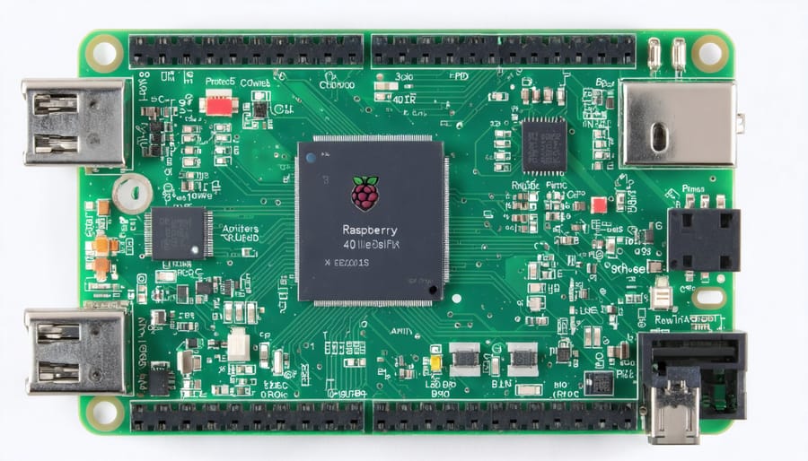
Master the Raspberry Pi 4 Model B GPIO pinout to unlock its full potential for your electronics projects. The 40-pin header delivers remarkable versatility through its combination of general-purpose I/O pins, specialized functions, and power rails. From home automation systems to custom sensors and educational projects, understanding the Raspberry Pi 4 Model B pinout architecture is essential for successful hardware integration.
Each pin serves a specific purpose: 26 GPIO pins for digital input/output, dedicated I2C, SPI, and UART interfaces for peripheral connections, and multiple power options including 3.3V and 5V rails. This careful arrangement enables endless possibilities while maintaining backward compatibility with previous Pi models. The dual-row header layout, combined with clearly defined pin numbering schemes (both physical and BCM), makes it straightforward to plan and implement your electronic interfaces with confidence.
The following guide explores the precise pin configurations that will bring your next project to life, from basic LED circuits to complex multi-sensor arrays.
Understanding the Raspberry Pi 4 GPIO Layout

Power Pins
The Raspberry Pi 4 Model B features several power pins that are crucial for powering both the board itself and external components. The board provides two voltage levels: 3.3V and 5V power rails. There are two 3.3V pins (physical pins 1 and 17) which can supply up to 50mA of current, making them ideal for powering low-power sensors and logic-level components. The two 5V pins (physical pins 2 and 4) connect directly to the board’s power input, subject to the power supply requirements of your setup.
For ground connections, the Pi 4 provides eight ground pins (physical pins 6, 9, 14, 20, 25, 30, 34, and 39) distributed across the GPIO header. These multiple ground points ensure convenient access when connecting various components and help maintain clean signal integrity in complex projects. It’s recommended to use the ground pin closest to your component’s power pin to minimize electrical noise and voltage drops.
Remember to never connect 5V components to 3.3V pins, as this could damage your Pi. Always verify your component’s voltage requirements before making connections.
General Purpose IO Pins
The Raspberry Pi 4 Model B features 40 programmable GPIO (General Purpose Input/Output) pins that serve as the board’s interface with the physical world. These pins can be configured as either inputs or outputs, allowing you to connect various sensors, buttons, LEDs, displays, and other electronic components.
Of the 40 pins, 26 are dedicated GPIO pins that can be controlled through programming. Each pin can handle 3.3V signals and can source or sink up to 16mA of current. Eight pins also support PWM (Pulse Width Modulation) output, which is perfect for controlling motor speed or LED brightness.
The GPIO pins include specialized functions like I2C, SPI, and UART interfaces, making it possible to communicate with a wide range of electronic devices and modules. For protection, these pins are designed with internal pull-up and pull-down resistors that can be enabled through software.
When working with GPIO pins, it’s essential to be mindful of voltage levels and current limitations to avoid damaging your Raspberry Pi or connected components. Many beginners start with simple LED projects before moving on to more complex applications.
Special Function Pins
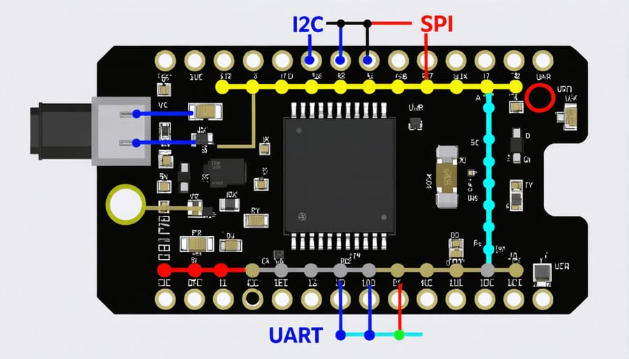
The Raspberry Pi 4 Model B offers a set of specialized pins within its 40-pin GPIO header that go beyond simple on/off signals. These special function pins support advanced communication protocols like I2C, SPI, UART, and PWM, enabling your Pi to interface with sensors, displays, motor controllers, and countless other peripherals. Understanding which pins serve double duty as protocol interfaces is essential for any project that requires precise timing, high-speed data transfer, or communication with components that speak these digital languages.
While standard GPIO pins work perfectly for buttons and LEDs, special function pins unlock more sophisticated capabilities. A temperature sensor might use I2C to send precise readings, while a servo motor relies on PWM signals for smooth positioning. These protocols handle the complex handshaking and timing automatically, so you don’t need to manually toggle pins thousands of times per second. The hardware built into the Raspberry Pi 4 takes care of the details once you’ve configured the pins correctly.
Most special function pins can still operate as regular GPIO if your project doesn’t need their advanced features. This flexibility means you’re not locked into one use case, though it’s worth planning your pinout strategy early. Once you enable I2C or SPI in the Pi’s configuration, those pins are reserved for that protocol and won’t respond to standard GPIO commands until you disable it again.
I2C Pins
The Raspberry Pi 4 Model B features two I2C (Inter-Integrated Circuit) communication channels that enable connectivity with various sensors, displays, and other I2C-compatible devices. The primary I2C bus uses pins GPIO 2 (SDA) and GPIO 3 (SCL), which are specifically designed for data and clock signals respectively. These pins support communication speeds up to 400 kHz in standard mode.
Located on physical pins 3 and 5 of the GPIO header, the I2C pins come with built-in pull-up resistors, making them ready to use without additional components in most cases. This makes them perfect for connecting common project components like OLED displays, temperature sensors, and real-time clock modules.
For more advanced projects requiring multiple I2C devices, the Pi 4 provides a secondary I2C bus on GPIO pins 0 and 1. This additional channel proves invaluable when you need to connect devices operating at different speeds or avoid address conflicts. Remember to enable I2C through the Raspberry Pi configuration tool before use, and always verify the voltage requirements of your I2C devices, as they should be compatible with the 3.3V logic level of the Pi.
import smbus
import time

# Initialize I2C bus (1 for Raspberry Pi 4, uses GPIO 2 and 3)
bus = smbus.SMBus(1)

# I2C device address (example: 0x48 for common sensors)
device_address = 0x48

# Write a byte to register 0x01
bus.write_byte_data(device_address, 0x01, 0x00)
time.sleep(0.1)

# Read a byte from register 0x00
data = bus.read_byte_data(device_address, 0x00)
print(f"Data read from device: {data}")

# Read a block of data (16 bytes) from register 0x00
block = bus.read_i2c_block_data(device_address, 0x00, 16)
print(f"Block data: {block}")
SPI Pins
The Raspberry Pi 4 Model B features two SPI (Serial Peripheral Interface) buses, enabling communication with various external devices. The primary SPI bus (SPI0) uses pins GPIO 8, 9, 10, and 11, while the secondary bus (SPI1) utilizes GPIO 16, 17, 18, and 19. These pins are essential for connecting devices like displays, sensors, and memory cards.
SPI0’s pins include MOSI (GPIO 10) for master output, MISO (GPIO 9) for master input, SCLK (GPIO 11) for clock signals, and CE0 (GPIO 8) for chip enable. This configuration allows for high-speed data transfer and is commonly used with LCD screens and ADC converters.
For projects requiring additional SPI devices, SPI1 provides similar functionality with MOSI (GPIO 20), MISO (GPIO 19), SCLK (GPIO 21), and CE0 (GPIO 18). This second bus is particularly useful when working with multiple SPI devices simultaneously, such as combining a display with temperature sensors or RFID readers.
Remember that SPI pins operate at 3.3V logic levels, so ensure your connected devices are compatible or use appropriate level shifters to prevent damage.
UART Pins
The Raspberry Pi 4 Model B features two UART (Universal Asynchronous Receiver-Transmitter) interfaces that enable serial communication with other devices. The primary UART (UART0) uses GPIO14 (TXD0) for transmitting data and GPIO15 (RXD0) for receiving data. These pins are essential for debugging, connecting to serial devices, or communicating with microcontrollers.
The secondary UART (UART1) utilizes GPIO14 (TXD1) and GPIO15 (RXD1), though it’s important to note that this interface is disabled by default and requires configuration to use. Both UART interfaces operate at 3.3V logic levels, so care should be taken when connecting to devices that use different voltage levels to avoid damage.
For beginners, the UART pins are particularly useful for connecting GPS modules, Arduino boards, or other serial devices. When working with these pins, remember that the TX (transmit) pin of your Raspberry Pi should connect to the RX (receive) pin of your target device, and vice versa.
To ensure reliable communication, make sure to use the correct baud rate settings and consider using a logic level converter when interfacing with 5V devices. The default baud rate for the Raspberry Pi’s serial console is 115200, though this can be adjusted in your software configuration.
Safety and Best Practices
When working with the Raspberry Pi 4’s GPIO pins, safety should always be your top priority. Here are essential guidelines to protect both yourself and your Pi:
Never connect or disconnect components while your Pi is powered on. Always shut down properly and unplug the power supply before making any hardware changes. This prevents short circuits and potential damage to your components.
Always verify the voltage requirements of your connected devices. The GPIO pins operate at 3.3V, and connecting components that require different voltages without proper level shifting can damage your Pi. Use voltage dividers or level shifters when necessary.
Be careful to avoid static electricity discharge. Before handling your Pi or any components, touch a grounded metal object to discharge any static buildup. Consider using an anti-static wrist strap for added protection.
Double-check your pin connections before powering on. Incorrect wiring can cause permanent damage. Use a multimeter to verify connections when in doubt, and consider creating a wiring diagram before starting your project.
Keep these best practices in mind:
– Use female-to-female jumper wires for secure connections
– Avoid loose connections that could cause shorts
– Never allow metal objects near exposed pins while powered
– Use GPIO pins within their rated current limits (16mA per pin)
– Include appropriate resistors when connecting LEDs
– Keep wires organized and labeled for easy troubleshooting
– Document your pin usage to avoid conflicts
Consider using a GPIO header protection board or breakout board for additional safety and convenience. These accessories can provide extra protection against shorts and make it easier to connect components properly.
Remember that the ground (GND) pins are not interchangeable with GPIO pins. Always use the designated ground pins for your circuit’s ground connections to ensure proper operation and prevent damage to your Pi.
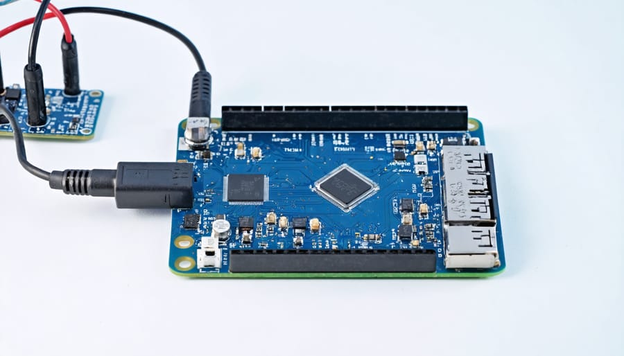
- Always power down your Pi completely before connecting or disconnecting components
- Verify that all components are compatible with 3.3V logic levels
- Use current-limiting resistors when connecting LEDs (typically 220-330Ω)
- Avoid shorting power pins to ground or to each other
- Use proper breadboards and quality jumper wires for reliable connections
- Consider using a protective case with GPIO access cutouts
- Keep a pin reference diagram handy to prevent wiring mistakes
Common Applications and Examples
The GPIO pins on the Raspberry Pi 4 Model B open up a world of possibilities for creative projects. One of the most popular applications is LED control, where users can create anything from simple blinking lights to complex RGB LED matrices. By connecting LEDs to GPIO pins through appropriate resistors, makers can build mood lighting systems, status indicators, or even holiday decorations.
For beginners, sensor integration provides an excellent starting point. Temperature and humidity sensors like the DHT11 or DHT22 can be easily connected to GPIO pins to create weather stations or environmental monitoring systems. Motion sensors (PIR) can be used for security systems or automated lighting controls, while distance sensors enable object detection for robotics projects.
Motor control is another common application, utilizing GPIO pins to drive DC motors, servo motors, or stepper motors. This enables the creation of automated blinds, pan-tilt camera mounts, or small robotic arms. The PWM-capable pins are particularly useful for precise motor speed control and servo positioning.
Display integration through GPIO pins allows makers to add screens to their projects. Popular options include LCD character displays using the I2C interface or larger OLED displays that can show detailed graphics and text. These are perfect for creating custom control panels, information displays, or retro gaming consoles.
Home automation enthusiasts often use GPIO pins to control relays, which can switch household appliances on and off. This enables projects like automated plant watering systems, smart garage door controls, or custom home security systems. The versatility of GPIO pins also allows for integration with various communication protocols like I2C, SPI, and UART, making it possible to connect multiple sensors and devices simultaneously.
For audio projects, the dedicated audio pins can be used to create music players, sound effects generators, or voice-controlled systems. Combined with other GPIO pins for buttons and displays, makers can build complete audio control interfaces.
Understanding the Raspberry Pi 4 Model B pinout is essential for unlocking the full versatility of Raspberry Pi in your projects. With its 40 GPIO pins offering various functions from simple digital I/O to specialized protocols like I2C and SPI, the possibilities are virtually endless. Remember to always double-check pin assignments before connecting components, and start with basic projects to build your confidence. Whether you’re creating an automated home system, building a retro gaming console, or developing an educational tool, the GPIO pins serve as your gateway to endless innovation. Don’t be afraid to experiment, but always follow proper safety guidelines to protect both your Pi and connected components. The Raspberry Pi community is vast and supportive, so share your projects and learn from others. As you become more comfortable with the pinout configuration, you’ll discover new and exciting ways to push the boundaries of what’s possible with this remarkable single-board computer.