

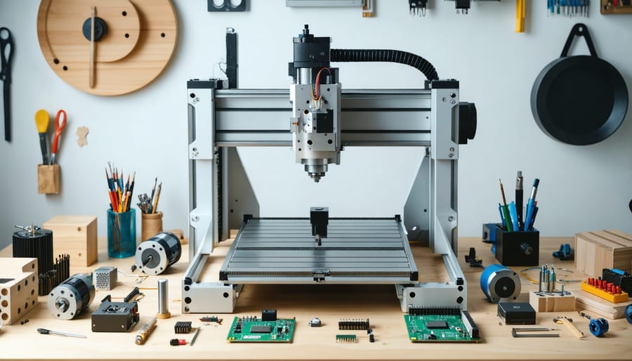
Transform your DIY manufacturing capabilities by building an open-source CNC milling machine – a powerful tool that empowers makers to create everything from custom Raspberry Pi cases to precision mechanical components. Modern open-source CNC platforms combine affordable hardware with powerful, freely available software, democratizing access to professional-grade manufacturing technology. Whether you’re prototyping circuit boards, crafting custom enclosures, or producing small-batch components, an open-source CNC mill offers unparalleled flexibility and control over your production process. By leveraging community-driven designs like RepRap Mills or OpenBuilds systems, makers can construct reliable CNC machines for a fraction of commercial alternatives’ cost while maintaining the freedom to modify and improve their systems as needed. This guide explores the essential components, build considerations, and practical applications of open-source CNC milling machines, with a special focus on creating Raspberry Pi-compatible components and accessories.
Why Open Source CNC for Raspberry Pi Components?
Cost Benefits and Customization
One of the most compelling advantages of open source CNC milling machines is their significant cost savings compared to commercial alternatives. While professional CNC mills can cost tens of thousands of dollars, building your own open source version typically ranges from $500 to $2,000, depending on your component choices and design complexity. This affordability makes it particularly attractive for hobbyists and small workshops creating custom components like industrial-grade Pi enclosures.
The customization potential is equally impressive. Users can modify both hardware and software components to meet specific needs, whether it’s expanding the working area, upgrading stepper motors for higher precision, or implementing custom G-code interpreters. This flexibility allows makers to start with a basic setup and gradually enhance capabilities as their skills and requirements grow.
Additionally, the open source nature encourages community-driven improvements and modifications. Users can access and contribute to a vast library of design files, firmware updates, and custom modifications, creating a collaborative ecosystem that continuously evolves and improves the technology.
Component Quality Control
Quality control in open source CNC milling machines is crucial for achieving precise and reliable results. Most DIY builds can achieve tolerances between 0.1mm to 0.05mm, which is suitable for many hobbyist applications and component creation. To maintain these precision levels, key factors include proper calibration of stepper motors, regular maintenance of linear rails, and verification of frame rigidity.
Many open source designs incorporate built-in quality control features, such as auto-leveling probes and real-time position monitoring. Users can verify component quality through test cuts on various materials, starting with softer options like wood or plastic before moving to metals. Common quality assurance methods include using dial indicators to check axis alignment, performing backlash measurements, and creating test pieces with known dimensions.
To ensure consistent results, it’s recommended to document all calibration settings and maintain a log of machine performance. Regular validation of dimensional accuracy using precision measuring tools helps identify any drift in machine performance over time. The open source community often shares calibration profiles and testing procedures, making it easier for builders to achieve and maintain high-quality output.
Popular Open Source CNC Designs
Desktop CNC Options
Desktop CNC machines offer an accessible entry point into the world of CNC milling, perfect for makers working from home workshops or small spaces. These compact units are ideal for crafting Raspberry Pi components and custom case designs, while maintaining professional-grade precision.
Popular open-source desktop options include the Lowrider CNC, which features a moving gantry design that can be built within a 4×4 foot footprint, and the Mostly Printed CNC (MPCNC), which uses 3D printed components to reduce costs. These machines typically handle materials like wood, plastic, and soft metals – perfect for prototyping Pi-related projects.
Key considerations for desktop CNC options include:
– Working area (typically 12×12 inches to 24×24 inches)
– Frame rigidity and vibration control
– Stepper motor size and power requirements
– Control board compatibility
– Dust collection solutions
Many desktop designs emphasize modularity, allowing makers to start with basic functionality and upgrade components as needed. This approach makes these machines particularly appealing for beginners while providing room for growth as skills develop. Their compact size and relatively quiet operation make them suitable for residential settings, while still maintaining enough capability for serious project work.
Larger Format Solutions
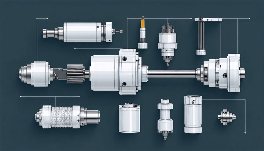
For makers seeking to produce larger components or tackle more ambitious projects, several open-source CNC milling machine designs cater to expanded work envelopes. The PrintNC design has gained significant traction in the maker community, offering a robust steel-frame construction that can accommodate workpieces up to 4×4 feet. This design uses readily available steel tubing and common components, making it both cost-effective and highly customizable.
Another popular large-format solution is the OpenBuilds OX CNC, which provides a modular approach to scaling. Users can easily modify the frame dimensions to suit their specific needs, with some builders successfully implementing work areas of up to 5×5 feet. The V-slot aluminum extrusion system makes assembly straightforward while maintaining good rigidity for larger projects.
The MPCNC (Mostly Printed CNC) platform also offers larger format possibilities, with many users successfully scaling the design to achieve working areas of 3×3 feet or more. While originally designed for smaller projects, strategic reinforcement and material choices allow for increased size without compromising stability.
When scaling up these designs, considerations must be made for increased motor power, stronger frame materials, and enhanced dust collection systems. Many builders opt for NEMA 23 or larger stepper motors to handle the increased mass and cutting forces involved in larger-format milling operations.
Essential Components and Software
Hardware Requirements
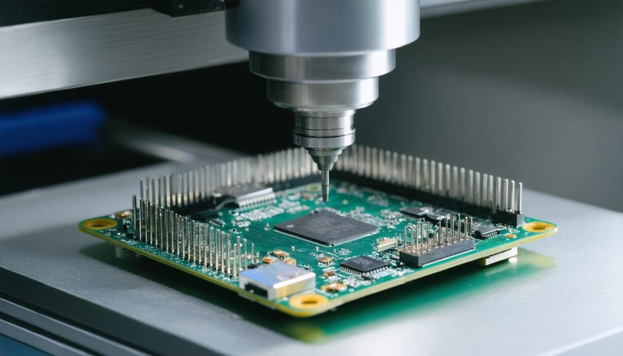
Building an open source CNC milling machine requires careful selection of mechanical components to ensure precision and reliability. The core hardware components include stepper motors, typically NEMA 23 or NEMA 17, which provide the necessary torque for accurate movement across all axes. You’ll need three to four of these motors depending on your design configuration.
The frame structure demands sturdy materials like aluminum extrusions (20x40mm or 40x40mm profiles) or steel tubing for rigidity. Linear motion components are crucial, including linear rails or rods with corresponding bearings for smooth, precise movement. Most builds utilize either ball screws or lead screws (8mm to 12mm diameter) for converting rotational motion to linear movement.
For the spindle, options range from basic rotary tools to dedicated CNC spindles (300W to 2.2kW). The choice depends on your intended materials and precision requirements. A solid mounting plate and appropriate collets are essential for tool holding.
Additional hardware requirements include:
– Limit switches for homing and safety
– Emergency stop button
– Mounting brackets and fasteners
– Cable carriers for wire management
– Cooling system for the spindle
– Anti-backlash nuts for improved accuracy
– End mill cutters in various sizes
Remember to source components from reputable suppliers to ensure compatibility and reliability. The quality of these mechanical components directly impacts the machine’s performance and longevity.
Control Electronics
The heart of any open source CNC milling machine lies in its control electronics, which orchestrate the precise movements necessary for precision component manufacturing. Most DIY builds utilize NEMA 23 or NEMA 17 stepper motors, which offer an excellent balance of torque and accuracy for small to medium-sized projects. These motors typically connect to specialized stepper drivers, with popular choices including the DRV8825 or TB6600 drivers, which handle the complex timing of motor phases.
At the core of the control system, many builders opt for Arduino-based solutions running GRBL firmware, though increasingly, Raspberry Pi configurations are gaining popularity for their enhanced processing capabilities. The most common control board choices include the Arduino CNC Shield, which offers plug-and-play compatibility, or more advanced options like the Smoothieboard for multi-axis control.
For power management, a 24V power supply rated between 350W to 400W typically provides sufficient energy for hobby-grade machines. It’s essential to incorporate emergency stop circuits and limit switches for safety and precise homing operations. Modern builds often include features like closed-loop feedback systems using encoders, which help maintain accuracy during high-speed operations and prevent missed steps.
Software Solutions
When it comes to controlling your open source CNC milling machine, several powerful software solutions are available, many of them free and community-supported. FreeCAD stands out as a popular choice for designing your projects, offering robust 3D modeling capabilities specifically tailored for mechanical parts and components. For converting your designs into machine instructions, LinuxCNC provides comprehensive control and a user-friendly interface that works particularly well with DIY setups.
Another excellent option is Fusion 360’s hobbyist license, which combines both CAD and CAM functionality in one package. While not fully open source, its free-for-personal-use model makes it accessible to makers and enthusiasts. For those preferring a completely open source workflow, OpenSCAM offers reliable G-code simulation to verify your toolpaths before actual cutting.
Universal G-Code Sender (UGS) serves as an excellent interface between your computer and the CNC machine, supporting various control boards and offering features like real-time visualization and manual machine control. For beginners, Carbide Create provides a straightforward approach to both design and toolpath generation, though with some limitations compared to more advanced solutions.
Remember that most of these tools support standard G-code output, ensuring compatibility with virtually any CNC controller board you choose to use in your build.
Setup and Calibration
Initial Assembly Tips
Before diving into the assembly process, there are several crucial considerations that will help ensure a smooth build of your open source CNC milling machine. First, create a clean, well-lit workspace with plenty of room to lay out components. Having a dedicated assembly area helps prevent lost parts and allows for better organization throughout the build process.
Document everything as you go – taking photos of each step and making notes about any modifications or adjustments you make. This documentation will be invaluable if you need to troubleshoot issues later or when performing maintenance.
Carefully inspect all components before assembly. Check for any damage or manufacturing defects, particularly in critical parts like linear rails, bearings, and structural elements. Pre-sorting hardware into clearly labeled containers will save time and reduce frustration during the build process.
Pay special attention to frame squareness during initial assembly. Even small misalignments can affect machine accuracy and performance. Use precision measuring tools like digital calipers and squares to verify dimensions and angles. Consider using a dial indicator to check for proper alignment of moving components.
Take your time with wiring and cable management. Proper routing of cables is essential for preventing interference and ensuring smooth axis movement. Use cable chains or flexible conduit to protect wires from wear, and leave enough slack for full range of motion without strain.
Don’t overtighten bolts and fasteners initially. Assemble components loosely first, then square and align everything before final tightening. This approach helps prevent binding and ensures smooth operation of moving parts. Remember, precision is more important than speed during the assembly process.

Calibration Process
Achieving precise results with your open source CNC milling machine requires careful calibration. Start by homing all axes to establish a reference point. Using a dial indicator, check the machine’s squareness by measuring the X and Y axes relative to each other. Adjust the frame and mounting brackets if needed until readings show less than 0.001″ deviation over 6 inches of travel.
Next, calibrate the stepper motors by setting the correct steps per millimeter. Mark a specific distance (typically 100mm) on your workbed and command the machine to move that exact distance. Measure the actual distance traveled and adjust the steps/mm value in your firmware accordingly. Repeat this process for all axes until measured movements match commanded distances within 0.1mm.
Check backlash by moving each axis back and forth repeatedly while measuring the play at direction changes. Adjust the lead screws and anti-backlash nuts to minimize any detected movement. For optimal accuracy, verify that belt tension (if using belt drives) is consistent and properly adjusted.
Calibrate the Z-axis touch probe if equipped, ensuring consistent triggering height across the work area. Use a flat piece of material with known thickness to set and verify the probe’s accuracy. Finally, perform a test cut on a sample piece, measuring the resulting dimensions with digital calipers. Fine-tune your settings based on these results.
Remember to document all calibration values and periodically recheck them, especially after heavy use or any maintenance work. This ensures your machine maintains its precision over time.
Creating Your First Pi Component
Let’s start your CNC milling journey by creating a simple but practical Raspberry Pi component. For this tutorial, we’ll design and mill a basic mounting bracket that can be used for various Pi case prototypes or project enclosures.
Begin by sketching your design on paper, keeping in mind the Pi’s dimensions (85.6mm × 56.5mm). A simple L-shaped bracket works well for beginners. Transfer your design to your preferred CAD software – FreeCAD is an excellent open-source option that works well with most CNC workflows.
For your first component, use a piece of 6mm acrylic or aluminum measuring approximately 100mm × 70mm. These materials are forgiving and ideal for beginners. Secure your material to the CNC bed using double-sided tape or mechanical clamps, ensuring it’s perfectly level.
Generate your G-code using a CAM program like PyCam or bCNC. For this project, we’ll use the following cutting parameters:
– Feed rate: 800mm/min
– Plunge rate: 300mm/min
– Cut depth per pass: 1mm
– Tool: 3mm flat end mill
Before starting the actual cut, perform a dry run with the spindle raised slightly above the material. This helps verify your toolpath and ensures there are no obvious programming errors. Once confident, proceed with the actual milling operation.
The entire process should take about 15-20 minutes. After completion, carefully remove your component and clean any rough edges with fine-grit sandpaper. Test-fit it with your Raspberry Pi to ensure proper alignment and mounting hole positions.
Remember to save your design files and cutting parameters – they’ll serve as valuable references for future projects. As you gain confidence, you can experiment with more complex designs and different materials.
Building an open source CNC milling machine represents an exciting journey into the world of digital fabrication and maker culture. Throughout this guide, we’ve explored the essential components, software options, and construction steps needed to create your own affordable and customizable CNC mill. By choosing open source solutions, you’re not just building a machine; you’re joining a vibrant community of makers who continuously improve and share their designs.
The next steps in your CNC journey should include joining online forums, experimenting with different materials, and perhaps even contributing your own modifications back to the community. Start with simple projects to build confidence, then gradually progress to more complex designs. Remember to prioritize safety features and regular maintenance to ensure your machine’s longevity.
Whether you’re planning to use your CNC mill for prototyping, hobby projects, or small-scale production, the skills and knowledge you gain from this endeavor will prove invaluable. The open source nature of these machines means you can always upgrade and modify your setup as your needs evolve, making it a truly future-proof investment in your maker journey.