
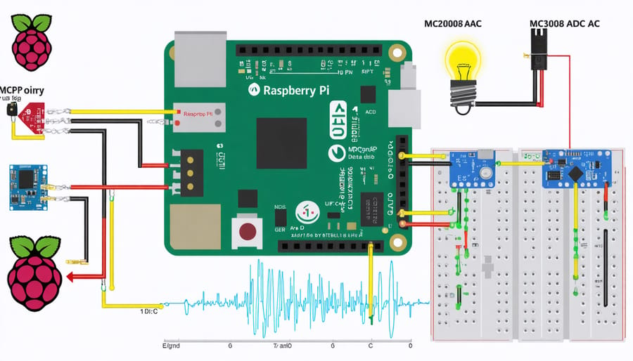
Transform your Raspberry Pi 4 into a powerful analog data acquisition system by connecting analog sensors through an MCP3008 ADC converter. The Raspberry Pi 4’s GPIO pins, combined with the right ADC hardware, enable precise monitoring of temperature, light intensity, soil moisture, and countless other analog signals with up to 10-bit resolution.
Master analog input implementation through three essential components: hardware setup (ADC connection to GPIO pins), software configuration (SPI interface enabling), and Python programming (data acquisition and processing). Whether you’re building environmental monitoring systems, creating interactive electronics, or developing IoT solutions, analog input capabilities unlock the Pi 4’s full potential for real-world sensing applications.
Quick setup requires just five components: a Raspberry Pi 4, MCP3008 ADC chip, breadboard, jumper wires, and your chosen analog sensor. Connect these components following the SPI protocol, install the required Python libraries, and start reading analog values in minutes. This versatile configuration supports sampling rates up to 200 kHz, making it suitable for both slow-changing environmental data and faster signal processing applications.
Understanding Analog Input on Raspberry Pi 4
Hardware Limitations
While the Raspberry Pi 4 specifications showcase impressive computing capabilities, one notable limitation is the absence of built-in analog input pins. This is because the Raspberry Pi’s processor, the BCM2711, is fundamentally a digital device designed for processing binary signals (0s and 1s). Adding analog-to-digital conversion circuitry directly to the board would have increased manufacturing costs and complexity while potentially compromising the board’s compact design.
Unlike microcontrollers such as Arduino, which commonly include built-in ADC (Analog-to-Digital Converter) capabilities, the Raspberry Pi prioritizes digital computing power and versatility. This design choice aligns with its primary role as a small computer rather than a dedicated microcontroller. However, this limitation doesn’t mean you can’t work with analog signals on your Pi. External ADC modules, HATs (Hardware Attached on Top), or specialized interfaces can be easily connected through the GPIO pins to enable analog input functionality when needed for your projects.
ADC Options for Raspberry Pi
Several ADC (Analog-to-Digital Converter) options are available for adding analog input capabilities to your Raspberry Pi 4. The most popular choice is the ADS1115, a 16-bit ADC that communicates via I2C protocol and offers four input channels. This versatile chip provides excellent precision and is ideal for various ADC implementation techniques.
Another reliable option is the MCP3008, an 8-channel 10-bit ADC that uses SPI communication. While it offers lower resolution than the ADS1115, it’s more affordable and suitable for basic sensing applications. For higher sampling rates, the MCP3208 provides 12-bit resolution with similar features.
HAT (Hardware Attached on Top) solutions like the Waveshare High-Precision AD/DA Board offer plug-and-play convenience with built-in voltage regulation and protection circuits. These HATs are excellent for beginners but typically cost more than individual ADC chips.
For basic projects, simple voltage divider circuits with the GPIO pins can work, though they’re less accurate and require careful implementation to avoid damaging your Pi.
Setting Up Your Analog Input System
Hardware Connection Guide
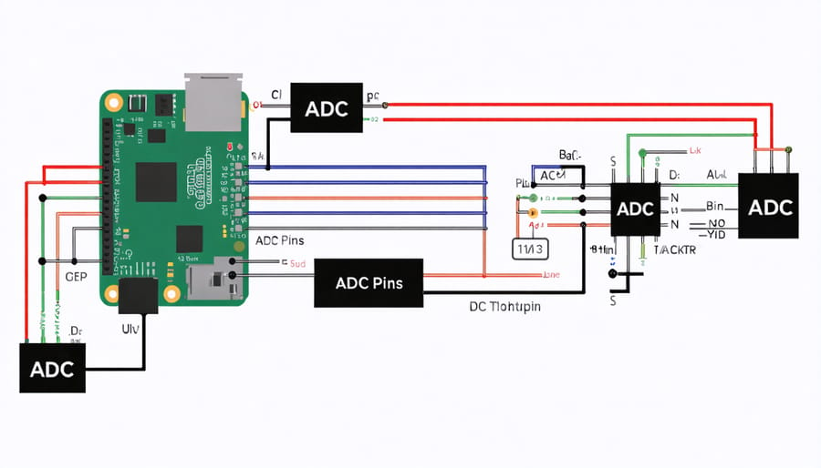
To connect an analog input to your Raspberry Pi 4, you’ll need an Analog-to-Digital Converter (ADC) since the Pi doesn’t have built-in analog inputs. We’ll use the popular MCP3008 ADC chip for this guide, as it’s reliable and widely available.
First, ensure you have all the necessary components:
– Raspberry Pi 4
– MCP3008 ADC chip
– Breadboard
– Jumper wires
– Your analog sensor or input device
Follow these connection steps:
1. Connect the MCP3008’s VDD (Pin 16) and VREF (Pin 15) to the Pi’s 3.3V power pin
2. Connect the MCP3008’s AGND (Pin 14) and DGND (Pin 9) to the Pi’s ground pin
3. Connect the MCP3008’s CLK (Pin 13) to the Pi’s GPIO 11 (SCLK)
4. Connect the MCP3008’s DOUT (Pin 12) to the Pi’s GPIO 9 (MISO)
5. Connect the MCP3008’s DIN (Pin 11) to the Pi’s GPIO 10 (MOSI)
6. Connect the MCP3008’s CS/SHDN (Pin 10) to the Pi’s GPIO 8 (CE0)
For your analog input device:
1. Connect its power to the Pi’s 3.3V
2. Connect its ground to the Pi’s ground
3. Connect its analog output to any of the MCP3008’s CH0-CH7 inputs (Pins 1-8)
Double-check all connections before powering up your Pi. Incorrect wiring could damage your components. Make sure the ADC chip is properly seated in the breadboard and all jumper wires are secure.
Software Installation and Configuration
To get started with analog input on your Raspberry Pi 4, you’ll need to install several essential software packages and libraries. Begin by updating your Raspberry Pi’s operating system by opening the terminal and running:
“`
sudo apt update
sudo apt upgrade
“`
Next, install the Python package manager (pip) if you haven’t already:
“`
sudo apt install python3-pip
“`
For reading analog inputs, we’ll primarily use the Adafruit CircuitPython libraries. Install them using:
“`
pip3 install adafruit-blinka
pip3 install adafruit-circuitpython-ads1x15
“`
These libraries provide support for various ADC (Analog-to-Digital Converter) modules, including the popular ADS1115 and ADS1015 chips. To enable I2C communication, which most ADC modules use, activate it through the Raspberry Pi configuration tool:
“`
sudo raspi-config
“`
Navigate to “Interface Options” and enable I2C. After enabling I2C, install the required tools:
“`
sudo apt install python3-smbus i2c-tools
“`
Verify your I2C setup by running:
“`
sudo i2cdetect -y 1
“`
This command should display a grid showing any connected I2C devices. If you see your ADC’s address (typically 0x48 for ADS1115), the installation was successful. Remember to reboot your Raspberry Pi after making these changes:
“`
sudo reboot
“`
With these software components installed and configured, your Raspberry Pi 4 is ready to start reading analog inputs through your chosen ADC module.
Programming Analog Input Reading
Basic Reading Operations
To read analog values using your MCP3008 ADC with the Raspberry Pi 4, you’ll need to first import the necessary libraries and set up your SPI communication. Here’s a basic Python script to get you started:
“`python
import spidev
import time
spi = spidev.SpiDev()
spi.open(0, 0)
spi.max_speed_hz = 1000000
def read_adc(channel):
adc = spi.xfer2([1, (8 + channel) << 4, 0])
data = ((adc[1] & 3) << 8) + adc[2]
return data
try:
while True:
value = read_adc(0) # Read from channel 0
voltage = value * (3.3 / 1023)
print(f"Raw Value: {value}, Voltage: {voltage:.2f}V")
time.sleep(0.5)
except KeyboardInterrupt:
spi.close()
```
This code initializes SPI communication, creates a function to read analog values, and continuously prints both raw ADC values (0-1023) and converted voltage readings. The sampling rate can be adjusted by modifying the sleep duration, and you can change the channel number (0-7) to read from different analog inputs on your MCP3008.
Remember to connect your analog sensor to the appropriate channel on the ADC before running the script. For more precise readings, consider implementing averaging or filtering techniques to reduce noise in your measurements.
Data Processing Techniques
When working with analog inputs on your Raspberry Pi 4, proper signal processing is crucial for accurate readings. The raw analog signals often contain noise and interference that need to be filtered out. One of the most common techniques is implementing a moving average filter in your code, which helps smooth out signal fluctuations by taking the average of multiple consecutive readings.
Digital filtering techniques can significantly enhance your Pi’s signal processing capabilities. The Kalman filter is particularly effective for real-time applications, as it can predict and correct signal values based on previous measurements. For slower-changing signals, a simple low-pass filter can effectively remove high-frequency noise while preserving the important data.
Python libraries like NumPy and SciPy offer powerful tools for signal processing. Using NumPy’s array operations, you can efficiently implement various filtering algorithms, while SciPy’s signal processing module provides ready-to-use filters and transforms. For basic projects, the median filter is an excellent choice to remove spurious spikes from your readings.
Remember to consider your sampling rate carefully – it should be at least twice the frequency of the signal you’re measuring (Nyquist rate). Over-sampling combined with decimation can improve your signal resolution, while proper scaling and calibration ensure accurate voltage readings.
Real-time Visualization
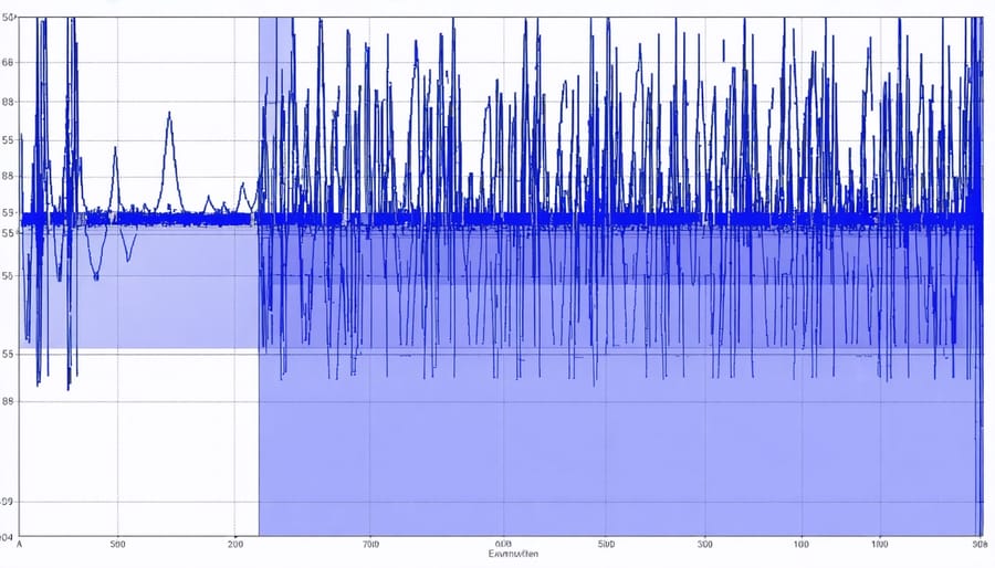
Real-time visualization of analog input data brings your Raspberry Pi projects to life by providing immediate feedback and monitoring capabilities. Python libraries like Matplotlib and PyQtGraph offer powerful tools for creating dynamic displays of your analog signals.
For basic visualization, you can use Matplotlib’s animation features to create updating line plots. Here’s a practical approach: initialize a figure with plt.figure(), create an animation object, and update it with incoming analog data at regular intervals. This method works well for slower sampling rates up to about 10Hz.
For faster updates and more responsive displays, PyQtGraph is the preferred choice. It’s optimized for real-time plotting and can handle update rates of 50Hz or higher smoothly. You can create scrolling waveform displays that show voltage changes over time, perfect for monitoring sensor outputs or audio signals.
To enhance your visualizations, consider adding features like:
– Auto-scaling axes to accommodate varying signal levels
– Multiple channel displays for comparing different inputs
– Threshold lines for trigger monitoring
– Data export capabilities for later analysis
For projects requiring data logging, combine your visualization with write operations to save the captured data to CSV files. This allows you to both monitor signals in real-time and preserve the data for future reference or analysis.
Remember to implement proper error handling and buffer management to prevent memory issues during extended monitoring sessions. A circular buffer structure works well for maintaining smooth performance while displaying continuous data streams.
Practical Applications and Tips
Common Use Cases
Analog input capabilities on the Raspberry Pi 4 enable a wide range of practical applications. One of the most popular uses is in environmental monitoring projects, where sensors measure temperature, humidity, and light levels. Home automation enthusiasts frequently use analog inputs to monitor soil moisture for smart gardening systems or track power consumption through current sensors.
In educational settings, analog inputs prove invaluable for physics experiments and data collection, allowing students to measure and analyze real-world phenomena. Makers and hobbyists often incorporate analog inputs in music projects, creating custom synthesizers or audio visualization tools. Industrial applications include production line monitoring, where analog sensors track pressure, flow rates, or machine vibrations.
Healthcare projects benefit from analog inputs when measuring biometric data like heart rate or muscle activity. Additionally, robotics enthusiasts use analog inputs for motor control feedback and position sensing, enabling precise movement and navigation in their projects.
Performance Optimization
To achieve optimal performance when working with analog inputs on your Raspberry Pi 4, consider implementing these proven optimization techniques. First, adjust your sampling rate based on your specific needs – higher rates provide more detailed data but consume more processing power. For most applications, a sampling rate between 100Hz and 1kHz offers a good balance.
Use hardware averaging by taking multiple readings in quick succession and calculating the mean value. This helps reduce noise and improves accuracy. Consider implementing a moving average filter in your code to smooth out readings and minimize outliers.
To enhance precision, calibrate your ADC regularly using known reference voltages. Remember to warm up your system for at least 5 minutes before taking critical measurements, as temperature variations can affect readings.
For projects requiring faster sampling, consider using direct memory access (DMA) to reduce CPU overhead. Additionally, running your sampling code at a higher priority can prevent system processes from interrupting your measurements.
If you’re working with multiple analog inputs, implement round-robin sampling rather than sequential reading to maintain consistent timing between channels. Finally, ensure proper shielding of your analog signal cables to minimize electromagnetic interference and improve signal quality.
Implementing analog input on your Raspberry Pi 4 opens up a world of possibilities for sensors, measurements, and interactive projects. We’ve covered the essential components needed, including the ADC converter options, wiring considerations, and programming methods to get accurate readings. Remember that while the MCP3008 and ADS1115 are popular choices, your specific project requirements should guide your ADC selection. Start with simple voltage measurements before advancing to more complex sensor implementations. If you’re new to this, practice with basic circuits first and gradually work your way up to more sophisticated applications. The Raspberry Pi community offers extensive support through forums and documentation, so don’t hesitate to seek help when needed. With these foundations in place, you’re well-equipped to begin creating your own analog input projects, from environmental monitoring systems to custom control interfaces.