

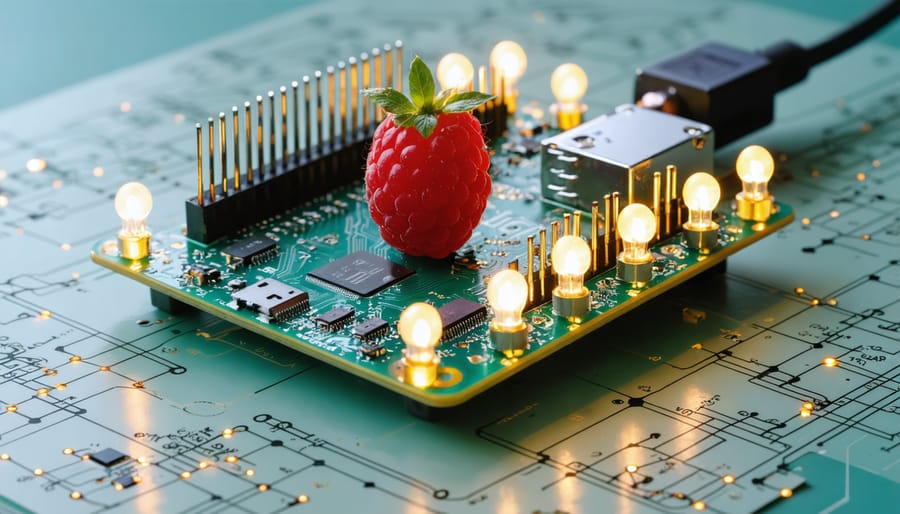
Control GPIO pins on your Raspberry Pi 4 Model B and earlier models through simple terminal commands that unlock powerful hardware interactions. The GPIO (General Purpose Input/Output) command-line interface enables direct pin manipulation without complex programming, making it perfect for quick prototyping and hardware testing. Master these commands to control LEDs, sensors, motors, and other electronic components with precise digital signals, transforming your Raspberry Pi into a versatile automation and sensing platform. Whether you’re building home automation systems, educational projects, or professional IoT solutions, understanding GPIO commands provides the foundation for limitless hardware interactions through your Pi’s 40-pin header.
Understanding GPIO Pins and Their Functions
GPIO Pin Numbering Systems
When working with GPIO pins on the Raspberry Pi, you’ll encounter two main numbering systems: BCM (Broadcom) and Physical pin numbering. The BCM system refers to the specific GPIO numbers assigned by the Broadcom chip, while Physical numbering simply counts across the pins from 1 to 40 in order.
For example, GPIO17 in BCM numbering corresponds to Physical pin 11. This distinction is crucial when writing GPIO commands, as you’ll need to specify which numbering system you’re using. Most GPIO commands use the -g flag to indicate BCM numbering.
To help visualize this:
– Physical numbering: Counts pins from top-left (1) to bottom-right (40)
– BCM numbering: Uses specific GPIO numbers (e.g., GPIO2, GPIO3, GPIO4)
When using the gpio command, you can switch between numbering systems:
– Use -1 for Physical numbering
– Use -g for BCM numbering
It’s recommended to stick with one numbering system throughout your project to avoid confusion and potential errors in your GPIO control commands.

Pin Modes and States
GPIO pins on the Raspberry Pi can be configured in three primary modes: input, output, and special function. In output mode, you can set pins to either HIGH (1) or LOW (0) state, allowing you to control LEDs, relays, or other external devices. When configured as inputs, pins can read external signals, such as button presses or sensor data.
To set a pin as output, use the command ‘gpio -g mode [PIN] out’, where [PIN] is your desired GPIO number. For input mode, use ‘gpio -g mode [PIN] in’. Some pins also support special functions like I2C, SPI, or PWM, which require specific configuration commands.
The current state of a pin can be read using ‘gpio -g read [PIN]’, while ‘gpio -g write [PIN] [STATE]’ sets the output state. For example, ‘gpio -g write 18 1’ sets GPIO18 to HIGH, turning on an attached LED.
Remember that input pins can be configured with internal pull-up or pull-down resistors using the ‘gpio -g mode [PIN] up’ or ‘gpio -g mode [PIN] down’ commands, which helps prevent floating inputs and ensures reliable signal reading.
Essential GPIO Commands for Control
Reading Pin States
Monitoring GPIO pin states is a crucial skill when working with Raspberry Pi, and it’s one of the essential terminal commands you’ll need to master. The gpio command provides several ways to read input pin states.
To read the state of a specific pin, use:
gpio read [PIN_NUMBER]
For example, to read GPIO pin 17:
gpio read 17
This command returns either 0 (LOW) or 1 (HIGH), indicating the current state of the pin.
For continuous monitoring of pin changes, you can use:
watch gpio read [PIN_NUMBER]
This updates the pin state every 2 seconds by default. To change the update interval, add the -n flag followed by the number of seconds:
watch -n 0.5 gpio read 17
To view the state of all GPIO pins at once, use:
gpio readall
This displays a comprehensive table showing the current configuration and state of every GPIO pin, including their modes (IN/OUT), values (HIGH/LOW), and physical pin numbers. This command is particularly useful when debugging multiple connections or verifying your pin setup.
Remember to configure your pins as inputs before reading them using:
gpio mode [PIN_NUMBER] in
Setting Pin Output
The GPIO command provides straightforward methods to control output pins on your Raspberry Pi. To set a pin to output mode and control its state, you’ll use a combination of simple commands.
First, set your desired pin as an output using:
“`bash
gpio -g mode [PIN_NUMBER] out
“`
Once configured, you can turn the pin ON (set to HIGH/1) with:
“`bash
gpio -g write [PIN_NUMBER] 1
“`
Or turn it OFF (set to LOW/0) with:
“`bash
gpio -g write [PIN_NUMBER] 0
“`
For example, to control an LED connected to GPIO pin 18:
“`bash
gpio -g mode 18 out
gpio -g write 18 1 # Turn LED on
gpio -g write 18 0 # Turn LED off
“`
You can also use the shorter pin notation without the -g flag, but this uses the Wiring Pi pin numbering scheme instead of the BCM numbering. For instance:
“`bash
gpio mode 1 out
gpio write 1 1
“`
These commands are ideal for quick testing or simple automation scripts. Remember that when setting pins as outputs, ensure nothing is connected that could cause a short circuit or damage your Pi. Always verify your pin numbers and connections before applying power.

Advanced GPIO Command Techniques
PWM Control Commands
Pulse Width Modulation (PWM) through GPIO pins allows you to control the duty cycle of digital signals, making it perfect for tasks like LED brightness control or motor speed adjustment. The Raspberry Pi offers hardware PWM on specific pins and software PWM on any GPIO pin.
To use hardware PWM, you’ll need to enable it first:
“`bash
gpio mode 1 pwm
“`
You can set the PWM range (default is 0-1024) using:
“`bash
gpio pwm-range 1000
“`
To control the PWM frequency:
“`bash
gpio pwmc
“`
To set the duty cycle, use the following command:
“`bash
gpio pwm
“`
For example, to set PIN 1 to 50% duty cycle with a range of 1000:
“`bash
gpio pwm 1 500
“`
Software PWM can be implemented on any GPIO pin, though it’s less precise than hardware PWM. To use software PWM:
“`bash
gpio -g mode
gpio -g pwm
“`
Remember that hardware PWM is available only on GPIO12 (PIN 1), GPIO13 (PIN 23), GPIO18 (PIN 12), and GPIO19 (PIN 24). For precise control, stick to these pins when working with PWM-sensitive applications like servo motors or LED dimming projects.
To stop PWM output, simply set the value to 0 or change the pin mode:
“`bash
gpio pwm
gpio mode
Interrupt Handling
The GPIO command line interface in Raspberry Pi provides powerful tools for handling interrupts and events, making it ideal for responsive projects and connecting with Arduino devices. To monitor GPIO pin changes, you can use the `gpio wfi` (wait for interrupt) command, which pauses program execution until a specified pin changes state.
Here’s how to set up basic interrupt handling:
1. Enable edge detection:
“`bash
gpio edge [PIN] [rising/falling/both]
“`
2. Monitor for changes:
“`bash
gpio wfi [PIN]
“`
For more detailed event monitoring, use the `gpio notify` command:
“`bash
gpio notify [PIN]
“`
This command will print timestamps when state changes occur, perfect for debugging and timing-sensitive applications.
To create a continuous monitoring script, combine these commands with a loop:
“`bash
while true; do
gpio wfi 17
echo “Pin 17 state changed!”
sleep 1
done
“`
For advanced users, the `-g` flag enables monitoring of multiple pins simultaneously:
“`bash
gpio notify -g 17,18,27
“`
These interrupt handling capabilities are essential for building responsive systems, such as security sensors, button interfaces, or automated monitoring solutions. Remember to properly debounce your inputs when working with physical switches to avoid false triggers.
Practical Project Examples
Here are some exciting real-world applications where GPIO commands prove invaluable in Raspberry Pi projects. Let’s start with a basic LED traffic light system – using simple GPIO commands to control three LEDs in sequence, simulating traffic signals. This project teaches timing control and basic pin manipulation while creating something visually engaging.
For home automation enthusiasts, you can create a smart garage door controller. By connecting a magnetic reed switch to detect the door’s position and using a relay module controlled via GPIO commands, you can monitor and control your garage door remotely. This project demonstrates both input and output pin functionality.
Weather station monitoring is another practical application. By connecting sensors for temperature, humidity, and pressure to GPIO pins, you can create automated data logging systems. The GPIO commands handle sensor reading and data processing, making it perfect for environmental monitoring projects.
For those interested in robotics, you can build your first robot project using GPIO commands to control motors and sensors. This involves using PWM signals for motor speed control and reading input from various sensors for navigation and obstacle avoidance.
Security system projects are also popular, combining motion sensors, cameras, and alarm systems. GPIO commands manage the sensors and trigger appropriate responses, such as capturing images or activating buzzers when motion is detected.
These projects demonstrate the versatility of GPIO commands in real-world applications, from simple LED control to complex automation systems. Each project builds upon basic GPIO concepts while creating practical, useful devices.
The GPIO command interface on Raspberry Pi opens up a world of possibilities for hardware control and automation. Throughout this guide, we’ve explored the essential commands for configuring and manipulating GPIO pins, from basic pin control to more advanced PWM operations. Remember that the command-line approach offers greater flexibility and control compared to graphical interfaces, making it invaluable for both simple projects and complex automated systems.
Whether you’re building a home automation system, creating educational projects, or developing IoT solutions, mastering GPIO commands will significantly enhance your Raspberry Pi experience. Don’t be afraid to experiment with different combinations of commands and create your own scripts to automate tasks. Start with simple LED controls, progress to sensors, and gradually work your way up to more complex projects involving multiple components and real-time interactions.
Keep this guide handy as a reference, but don’t let it limit your creativity. The Raspberry Pi community is constantly developing new ways to utilize GPIO functionality, and your next project could inspire others. Happy tinkering!