
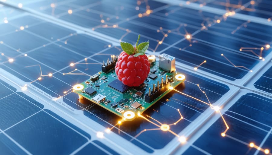
Unleash the full potential of your Raspberry Pi Zero’s GPIO pins to create powerful smart automation workflows and renewable energy monitoring systems. The 40-pin GPIO header serves as your gateway to endless possibilities, from solar panel optimization to sophisticated sensor networks. Whether you’re building an off-grid energy monitor or implementing advanced power management solutions, the Pi Zero’s compact form factor and versatile GPIO capabilities make it the perfect platform for sustainable technology projects. Master these pins to interface with voltage sensors, control relay switches, and process real-time environmental data – all while consuming minimal power, making it ideal for solar-powered applications. Connect, monitor, and automate your renewable energy systems with precision using this powerful yet energy-efficient microcomputer.
Understanding GPIO on Raspberry Pi Zero
GPIO Pin Layout and Specifications
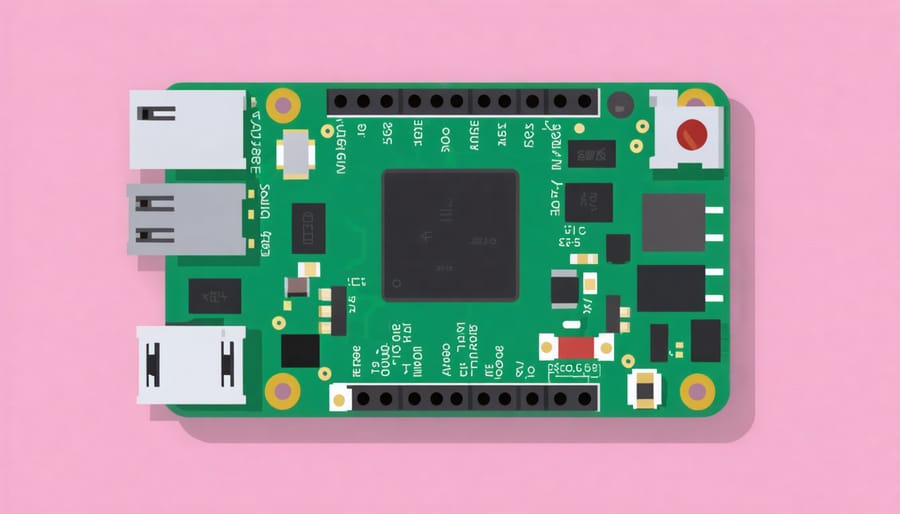
The Raspberry Pi Zero features 40 GPIO pins arranged in two rows of 20, identical to the layout found on larger Pi models. These pins include specialized functions such as I2C, SPI, and UART communication protocols, along with standard input/output capabilities. Of these, 26 are general-purpose pins that can be programmed for digital input or output.
The GPIO pins operate at 3.3V logic level, with a maximum current draw of 16mA per pin and a total maximum current of 51mA across all GPIO pins. It’s crucial never to apply 5V directly to these pins, as this can damage your Pi Zero. Ground pins (GND) and power pins supplying 3.3V and 5V are also available for powering external components.
For easy identification, pins follow the BCM (Broadcom) numbering scheme. The physical pin layout starts from the top-left corner, with odd numbers on the left and even numbers on the right. Notable pins include GPIO 2 and 3 for I2C communication, GPIO 14 and 15 for UART, and GPIO 7, 8, 9, 10, and 11 for SPI interfaces, making the Pi Zero versatile for various electronic projects.
Required Components and Safety Considerations
To safely work with GPIO pins on your Raspberry Pi Zero, you’ll need several essential components. Start with a Raspberry Pi Zero board, a reliable 5V micro-USB power supply rated at least 1A, and a microSD card (8GB or larger) with Raspberry Pi OS installed.
For GPIO connections, gather male-to-female jumper wires, a breadboard for prototyping, and basic electronic components like LEDs (with appropriate resistors, typically 220-330Ω), push buttons, and sensors relevant to your project.
Safety is paramount when working with GPIO pins. Always connect components with the Pi powered off to prevent short circuits. Use a multimeter to verify voltages when troubleshooting. Remember that GPIO pins operate at 3.3V – never apply higher voltages directly to them as this can damage your Pi Zero.
Keep your workspace clean and organized to avoid accidental shorts. Consider using a GPIO reference card or pinout guide to prevent incorrect connections. For added protection, a GPIO breakout board with built-in protection circuits is recommended, especially for beginners.
Setting Up GPIO for Solar Energy Monitoring
Installing Required Libraries
Before diving into GPIO projects on your Raspberry Pi Zero, you’ll need to install several essential libraries to enable proper communication with the GPIO pins. Start by updating your system packages using the terminal commands:
“`
sudo apt-get update
sudo apt-get upgrade
“`
Next, install the Python GPIO library (RPi.GPIO) which provides the fundamental GPIO control functionality:
“`
sudo apt-get install python3-rpi.gpio
“`
For more advanced projects, you might want to install the GPIO Zero library, which offers a simpler, more intuitive interface:
“`
sudo apt-get install python3-gpiozero
“`
If you plan to work with I2C or SPI devices, install these additional packages:
“`
sudo apt-get install python3-smbus
sudo apt-get install i2c-tools
“`
To verify your installations, open Python and try importing the libraries:
“`python
import RPi.GPIO as GPIO
from gpiozero import LED
“`
If no errors appear, you’re ready to start working with GPIO pins on your Raspberry Pi Zero. Remember to run your GPIO scripts with sudo privileges to ensure proper access to the hardware.
Connecting Solar Sensors
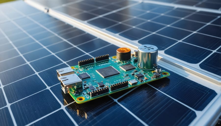
To monitor solar panel performance, you’ll need to connect voltage and current sensors to your Raspberry Pi Zero’s GPIO pins. The INA219 sensor is an excellent choice for this setup, offering both voltage and current measurements through the I2C interface.
Start by connecting the INA219 sensor’s VCC pin to the Pi’s 3.3V power pin (physical pin 1) and the GND pin to any ground pin (such as physical pin 6). For I2C communication, connect the SDA pin to GPIO 2 (physical pin 3) and SCL to GPIO 3 (physical pin 5).
For monitoring solar panel output, connect the V+ and V- terminals of your solar panel to the INA219’s V+ and V- pins respectively. Make sure to include appropriate fuses and voltage regulators if your solar panel’s output exceeds 26V, as this is the maximum input voltage for the INA219.
To improve accuracy, use twisted-pair cables for the I2C connections and keep wiring as short as possible. If you’re monitoring multiple solar panels, you can connect additional INA219 sensors to the same I2C bus, but each must have a unique I2C address.
Before powering up, double-check all connections and ensure proper polarity. Wrong connections could damage both your sensors and the Raspberry Pi Zero. Once connected, enable I2C in your Raspberry Pi’s configuration settings using raspi-config.
Basic GPIO Programming
Reading sensor data through GPIO pins on the Raspberry Pi Zero is straightforward with Python. Here’s a basic example using the RPi.GPIO library to read temperature data:
“`python
import RPi.GPIO as GPIO
import time
# Set GPIO mode to BCM
GPIO.setmode(GPIO.BCM)
# Define the sensor pin
SENSOR_PIN = 17
# Setup the pin as input
GPIO.setup(SENSOR_PIN, GPIO.IN)
while True:
# Read sensor data
sensor_value = GPIO.input(SENSOR_PIN)
print(f”Sensor reading: {sensor_value}”)
time.sleep(1)
“`
This simple code forms the foundation for more complex applications, including automated task management systems. For analog sensors, you’ll need an analog-to-digital converter (ADC) since the Pi Zero only has digital GPIO pins. Remember to always clean up your GPIO settings when your program exits:
“`python
GPIO.cleanup()
“`
This prevents potential issues in future GPIO operations and protects your Pi Zero from electrical problems.
Real-time Energy Optimization
Data Collection Scripts
Here’s a simple Python script that demonstrates how to collect solar panel performance data using GPIO pins on your Raspberry Pi Zero. First, connect your solar panel’s voltage output to GPIO pin 18 through a voltage divider circuit to protect your Pi:
“`python
import RPi.GPIO as GPIO
import time
import csv
from datetime import datetime
# Configure GPIO settings
GPIO.setmode(GPIO.BCM)
GPIO.setup(18, GPIO.IN)
def collect_solar_data():
with open(‘solar_data.csv’, ‘a’, newline=”) as file:
writer = csv.writer(file)
voltage = GPIO.input(18)
timestamp = datetime.now().strftime(‘%Y-%m-%d %H:%M:%S’)
writer.writerow([timestamp, voltage])
def main():
try:
while True:
collect_solar_data()
time.sleep(300) # Collect data every 5 minutes
except KeyboardInterrupt:
print(“Data collection stopped”)
finally:
GPIO.cleanup()
if __name__ == “__main__”:
main()
“`
This script records voltage readings every five minutes and saves them to a CSV file. To enhance your data collection, you can add multiple sensors by connecting them to different GPIO pins. For temperature monitoring, add a DHT22 sensor to GPIO pin 23:
“`python
import Adafruit_DHT
sensor = Adafruit_DHT.DHT22
pin = 23
def read_temperature():
humidity, temperature = Adafruit_DHT.read_retry(sensor, pin)
return temperature if temperature is not None else 0
“`
Remember to install the necessary libraries using pip before running these scripts. For long-term monitoring, consider adding error handling and automatic restart capabilities to ensure continuous data collection.
Automated Load Management
The Raspberry Pi Zero’s GPIO pins can be effectively utilized to create an intelligent load management system that optimizes power distribution across multiple devices. By implementing workflow automation through GPIO controls, you can efficiently manage power consumption based on priority and availability.
To set up automated load management, start by connecting relay modules to your GPIO output pins. These relays act as programmable switches, allowing you to control the power supply to different devices. A typical setup might use GPIO pins 17, 27, and 22 for controlling three separate circuits, each managing different load priorities.
Here’s a basic implementation approach:
1. Connect your relay modules to the designated GPIO pins
2. Wire your devices through the normally-open (NO) contacts of the relays
3. Use Python’s RPi.GPIO library to control the relays
The system can be programmed to monitor total power consumption and automatically disconnect non-essential loads when power usage exceeds predetermined thresholds. For example:
“`python
import RPi.GPIO as GPIO
import time
GPIO.setmode(GPIO.BCM)
GPIO.setup(17, GPIO.OUT) # High priority
GPIO.setup(27, GPIO.OUT) # Medium priority
GPIO.setup(22, GPIO.OUT) # Low priority
def manage_loads(power_available):
if power_available < threshold_low:
GPIO.output(22, GPIO.HIGH) # Disconnect low priority
elif power_available < threshold_medium:
GPIO.output(27, GPIO.HIGH) # Disconnect medium priority
else:
GPIO.output((17,27,22), GPIO.LOW) # Connect all loads
```
This system can be enhanced by incorporating power monitoring sensors and real-time data analysis to make intelligent decisions about load shedding and restoration. The GPIO pins can also be configured to respond to external triggers, such as time-based schedules or environmental conditions, making it ideal for solar power systems and other renewable energy applications.
Performance Monitoring Dashboard
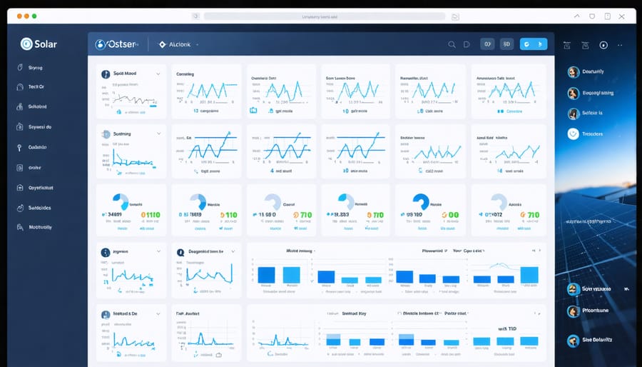
Creating a web-based dashboard for monitoring your Raspberry Pi Zero’s GPIO performance can transform it into a smart monitoring system that’s both practical and informative. Using Flask, a lightweight Python web framework, we can build an intuitive interface that displays real-time GPIO status and sensor readings.
Start by installing Flask and creating a basic server script that reads GPIO pin states. The dashboard can display digital pin status through simple toggle switches and analog readings through dynamic charts using JavaScript libraries like Chart.js. This visualization makes it easy to track changes and identify patterns in your GPIO data.
To enhance functionality, implement WebSocket connections for real-time updates without page refreshes. This allows your dashboard to instantly reflect any GPIO state changes or sensor reading fluctuations. Add features like pin control buttons, allowing you to toggle GPIO outputs directly from the web interface.
For data logging capabilities, incorporate SQLite database integration to store historical GPIO activities. This enables trend analysis and helps identify potential issues before they become problems. Create custom alerts that trigger when specific conditions are met, such as when a sensor reading exceeds predetermined thresholds.
The dashboard can be accessed from any device on your local network, making it convenient to monitor your Raspberry Pi Zero’s GPIO performance remotely. Consider adding authentication to secure your interface and prevent unauthorized access. For more advanced users, implement API endpoints to allow integration with other automation systems or custom applications.
Remember to optimize the dashboard for mobile devices, ensuring you can monitor your GPIO pins even when you’re away from your desk.
The Raspberry Pi Zero’s GPIO capabilities have proven to be a game-changer in the realm of renewable energy systems, offering an affordable yet powerful solution for monitoring and controlling sustainable energy projects. By leveraging these GPIO pins, makers and engineers can create sophisticated solar tracking systems, wind turbine monitoring stations, and smart grid integration solutions at a fraction of the cost of traditional industrial systems.
The combination of the Pi Zero’s compact size, low power consumption, and versatile GPIO interface makes it an ideal platform for developing energy-efficient monitoring solutions. Whether it’s collecting data from solar panels, managing battery charging systems, or optimizing energy distribution, the possibilities are virtually limitless.
Looking ahead, the future of Pi Zero GPIO in renewable energy applications appears incredibly promising. As more developers contribute to open-source projects and share their innovations, we can expect to see increasingly sophisticated implementations. The emergence of machine learning and AI capabilities on the Pi platform could lead to more intelligent energy management systems, predictive maintenance solutions, and automated optimization algorithms.
For hobbyists and professionals alike, the Pi Zero’s GPIO system continues to lower the barrier to entry for renewable energy projects while maintaining the flexibility needed for advanced applications. This democratization of renewable energy technology through accessible hardware like the Pi Zero is helping drive innovation and adoption of sustainable energy solutions worldwide.