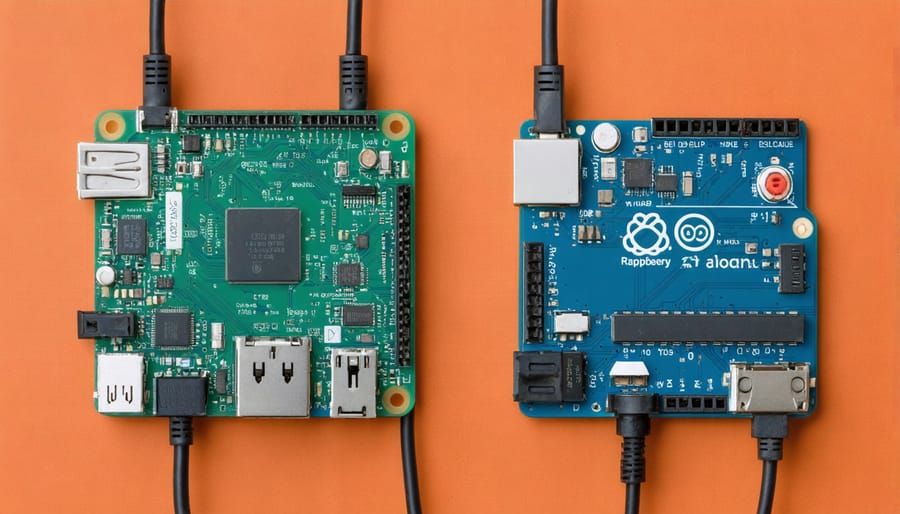
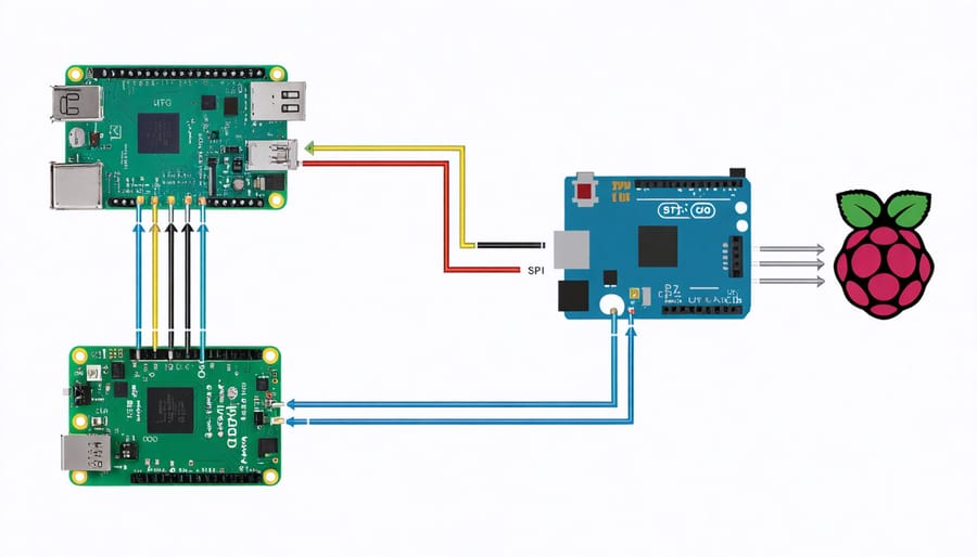
Connect your Raspberry Pi and Arduino using USB, allowing serial communication between the boards. Set up your Raspberry Pi as the master device to send commands, and configure the Arduino as the slave to execute those instructions. Use the pySerial library on the Pi to establish serial communication, and the Serial library on the Arduino to read incoming data. Create a simple robotics with Raspberry Pi project, such as controlling an LED or motor connected to the Arduino, to demonstrate successful communication between the two boards.
Understanding the Basics

What is a Raspberry Pi?
The Raspberry Pi is a credit card-sized single-board computer that has revolutionized the world of hobbyist electronics and computing. Despite its compact size, the Raspberry Pi 4 packs a punch with a quad-core ARM Cortex-A72 processor, up to 8GB of RAM, and a variety of connectivity options including USB, Ethernet, and Wi-Fi. Its versatility and affordability have made it a go-to choice for DIY projects, home automation, media centers, and even as a lightweight desktop computer replacement. The Raspberry Pi runs on Linux-based operating systems and supports a wide range of programming languages, making it an excellent tool for learning to code and bringing creative ideas to life.
What is an Arduino?
An Arduino is a popular open-source microcontroller board that enables users to create interactive electronic projects. It consists of a programmable circuit board and an integrated development environment (IDE) for writing and uploading code. Arduinos are versatile and can be used to control various components such as LEDs, sensors, motors, and displays. They are capable of reading inputs from the environment and controlling outputs based on programmed instructions. Typical Arduino applications include home automation, robotics, data logging, and creating custom electronic devices. With a large community and extensive libraries, Arduinos are accessible to beginners and offer endless possibilities for experienced developers. Their affordability and ease of use make them a popular choice for hobbyists, students, and professionals alike. When combined with a Raspberry Pi, Arduinos can be used to create powerful projects that leverage the strengths of both platforms.

Communication Methods
Serial Communication (UART)
Serial communication (UART) is a straightforward method to establish a connection between a Raspberry Pi and an Arduino. To set up serial communication, connect the TX pin of the Raspberry Pi to the RX pin of the Arduino, and the RX pin of the Raspberry Pi to the TX pin of the Arduino. Additionally, connect the ground pins of both boards together.
On the Raspberry Pi, use the pySerial library to send and receive data. Install it by running `pip install pyserial` in the terminal. Here’s a Python code example that sends a message to the Arduino:
“`python
import serial
ser = serial.Serial(‘/dev/ttyACM0′, 9600) # Change the port if necessary
ser.write(b’Hello, Arduino!’)
ser.close()
“`
On the Arduino side, use the `Serial` library to read the incoming data. Here’s an Arduino sketch that reads the message sent by the Raspberry Pi:
“`cpp
void setup() {
Serial.begin(9600);
}
void loop() {
if (Serial.available() > 0) {
String message = Serial.readStringUntil(‘\n’);
Serial.print(“Received message: “);
Serial.println(message);
}
}
“`
With these code examples, you can establish a basic serial communication between your Raspberry Pi and Arduino. You can expand on this foundation to create more complex projects that involve bidirectional communication and data exchange between the two boards.
I2C Communication
I2C (Inter-Integrated Circuit) is a popular two-wire communication protocol that allows the Raspberry Pi and Arduino to exchange data. It uses a master-slave architecture, with the Raspberry Pi typically acting as the master and the Arduino as the slave. To set up I2C communication, connect the SDA (data) and SCL (clock) pins between the boards, along with a common ground. On the Raspberry Pi, enable I2C through the Raspberry Pi Configuration tool or by editing the config.txt file.
With the wiring in place, you can use the smbus library in Python on the Raspberry Pi to send and receive data. Install it using pip: sudo pip install smbus. On the Arduino side, use the Wire library, which comes pre-installed with the Arduino IDE.
Here’s a simple example of sending data from the Raspberry Pi to the Arduino:
Raspberry Pi (Python):
import smbus

bus = smbus.SMBus(1)

arduino_address = 0x04

data = 42

bus.write_byte(arduino_address, data)
Arduino (C++):
#include

void setup() {

  Wire.begin(0x04);

  Wire.onReceive(receiveEvent);

}
void loop() {}
void receiveEvent(int bytes) {
int received = Wire.read();
// Process the received data
}
This example demonstrates the basics of I2C communication between the Raspberry Pi and Arduino, providing a foundation for more complex projects and interactions.
SPI Communication
SPI (Serial Peripheral Interface) is a synchronous serial communication protocol that enables high-speed data transfer between a master device (usually the Raspberry Pi) and one or more slave devices (like the Arduino). It utilizes four wires: MOSI (Master Out Slave In), MISO (Master In Slave Out), SCLK (Serial Clock), and SS (Slave Select). To implement SPI communication between the Raspberry Pi and Arduino, connect the MOSI, MISO, and SCLK pins of both boards together. Use a separate SS pin for each slave device connected to the master.
On the Raspberry Pi, you can use the spidev Python library to control the SPI interface. First, enable SPI using raspi-config or by adding “dtparam=spi=on” to /boot/config.txt. Then, install the spidev library with “pip install spidev”. In your Python script, import the library and create an SPI object to start communication.
For the Arduino side, use the SPI library, which comes pre-installed with the Arduino IDE. In your sketch, include the SPI library and set the SS pin as an output. In the setup() function, call SPI.begin() to initialize communication. Use SPI.transfer() to send and receive data between the boards.
By following these steps and referring to the examples provided in each library’s documentation, you can successfully establish SPI communication between your Raspberry Pi and Arduino, opening up a world of possibilities for your projects.
Practical Project Example
Project Overview and Materials
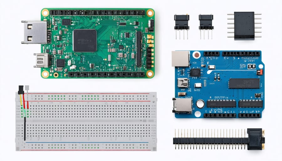
In this hands-on project, we’ll explore how to establish communication between a Raspberry Pi and an Arduino, two popular development boards in the maker community. By connecting these boards, you can harness the processing power of the Pi and the real-time capabilities of the Arduino to create innovative projects. To get started, you’ll need the following components:
– Raspberry Pi board (any model)
– Arduino board (e.g., Uno, Nano, Mega)
– USB cable to connect the Arduino to the Pi
– Breadboard and jumper wires
– LEDs and resistors (optional, for testing)
With these materials ready, let’s dive into the fascinating world of Raspberry Pi-Arduino communication and bring your ideas to life!
Wiring and Setup
To wire the Raspberry Pi and Arduino for communication, you’ll need a few basic components:
- Raspberry Pi board (any model)
- Arduino board (Uno or similar)
- Breadboard
- Jumper wires
- USB cable (to power the Arduino)
Begin by connecting the ground (GND) pins of both boards using a jumper wire. This establishes a common ground reference. Next, link the Raspberry Pi’s GPIO pins to the Arduino’s digital pins based on your chosen communication protocol.
For UART, connect the Raspberry Pi’s TX pin (GPIO14) to the Arduino’s RX pin, and the Raspberry Pi’s RX pin (GPIO15) to the Arduino’s TX pin. If using I2C, join the Raspberry Pi’s SDA (GPIO2) and SCL (GPIO3) pins to the Arduino’s corresponding SDA and SCL pins. For SPI, wire the Raspberry Pi’s MOSI (GPIO10), MISO (GPIO9), and SCLK (GPIO11) pins to the Arduino’s MOSI, MISO, and SCK pins respectively, plus a chip select (CS) pin of your choice.
Power the Arduino via USB and the Raspberry Pi through its dedicated power input. With the wiring complete, you’re ready to dive into programming the communication between the two boards!

Code Walkthrough
Here’s the code walkthrough for the Raspberry Pi (Python) and Arduino (C++) sides of the communication:
# Raspberry Pi (Python)
import serial

ser = serial.Serial('/dev/ttyACM0', 9600)  # Initialize serial communication

while True:
    message = input("Enter a message: ")  # Get user input
    ser.write(message.encode())  # Send the message to Arduino

    if ser.in_waiting > 0:
        response = ser.readline().decode('utf-8').rstrip()  # Read Arduino's response
        print("Arduino says: ", response)  # Print the response
The Python code initializes serial communication with the Arduino, prompts the user for a message, sends it to the Arduino, and waits for a response. It reads the incoming data and prints Arduino’s reply.
// Arduino (C++)
String message;

void setup() {
  Serial.begin(9600);  // Initialize serial communication
}

void loop() {
  if (Serial.available()) {
    message = Serial.readStringUntil('\n');  // Read incoming message
    Serial.print("Raspberry Pi says: ");
    Serial.println(message);  // Print the message

    Serial.println("Message received!");  // Send a response back
  }
}
The Arduino code listens for incoming serial data. When a message is received, it reads it, prints the message to the serial monitor, and sends a confirmation response back to the Raspberry Pi.
This simple back-and-forth communication forms the basis for exchanging data between the boards. You can expand upon this foundation to create more complex interactions tailored to your specific project requirements.
Testing and Troubleshooting
To verify your project is working correctly, start by double-checking all connections between the Raspberry Pi and Arduino. Ensure the TX and RX pins are correctly wired and the ground pins are connected. Use serial monitoring tools like the Arduino IDE’s Serial Monitor or Python’s pySerial library to send test messages and confirm successful communication.
Common issues to watch out for include incorrect baud rate settings, mismatched pin connections, and incompatible voltage levels. If encountering problems, try reducing the baud rate, rechecking wiring, and using level shifters for different voltage levels. Debugging with print statements and error handling in your code can also help identify and resolve issues.
In summary, communicating between a Raspberry Pi and Arduino opens up a world of possibilities for innovative projects. By leveraging the strengths of each board – the Pi’s processing power and the Arduino’s real-time capabilities – you can create sophisticated systems that interact with the physical world. Whether you choose serial, I2C, or SPI communication, the key is understanding the protocols and wiring connections involved. The hands-on project example demonstrates the basics, but there’s so much more to explore. For more advanced applications, consider exploring projects like transforming your Raspberry Pi into a powerful router or creative hacking projects. So go ahead, experiment with different sensors, actuators, and communication methods to bring your own unique ideas to life. The only limit is your imagination!


